I would say impedance not inductance, inductance is determined by the lead positions. This is where bus routing (double sided broadside coupled routing or twisted pair cables helps reduce inductance.
Anything that will reduce the voltage between the two amp board grounds is good. Impedance includes capacitance.
Last edited:
I would say impedance not inductance, inductance is determined by the lead positions. This is where bus routing (double sided broadside coupled routing or twisted pair cables helps reduce inductance.
I think Mark was trying to help the OP rather than showing off his own knowledge 😉
Jan
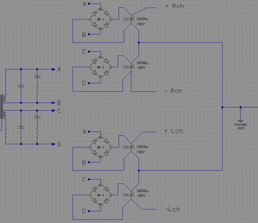
I was trying to get some isolation between the amps via the caps and diode bridges for more of a monoblock psu
Attachments

You still have parallel diodes and paths. If the return diodes, BR3/4 switch faster than the return diodes BR1/2 then the current will flow back via that pathway.
I was trying to get some isolation between the amps via the caps and diode bridges for more of a monoblock psuThanks, I was just thinking the same thing - why can't two CRC blocks be paralleled from two secondaries? This should improve stereo separation and soundstage.
I will try it. Just need to order another bunch of MUR rectifiers. 🙂
I do want to say thank you to all who have participated in this thread as you have all been very helpful and kept a great attitude - it has been very educational for me and I am not going to make these mistakes again.
No. As Mark Whitney says, you lose control of where the return currents go. The likely result is buzz and reduced stereo separation. Maybe this ought to be in a sticky thread?xrk971 said:Thanks, I was just thinking the same thing - why can't two CRC blocks be paralleled from two secondaries? This should improve stereo separation and soundstage.
You can run two channels from two separate PSUs fed from two separate sets of secondaries. Or you can run two channels from one PSU fed from one set of secondaries. Attempts to form a hybrid of these two options are frequently attempted but almost always fail, for the simple reason that two things cannot be both separate and joined and if you intend joining things you need to do it in the right way.
So a junk chinese smps still performs better, but we think it sounds worse.
Nice conclusion ?
This is what an increasing number of people seem to be finding now. Linear power supplies are rapidly becoming passe? Many are using them very successfully with JLH amplifiers
Both types can be poor performers when implemented poorly.
Learning to make either type perform well (ie. a professional effort) is possible for diy - especially nowadays with internet access to resources, and easy to afford test tools.
Learning to make either type perform well (ie. a professional effort) is possible for diy - especially nowadays with internet access to resources, and easy to afford test tools.
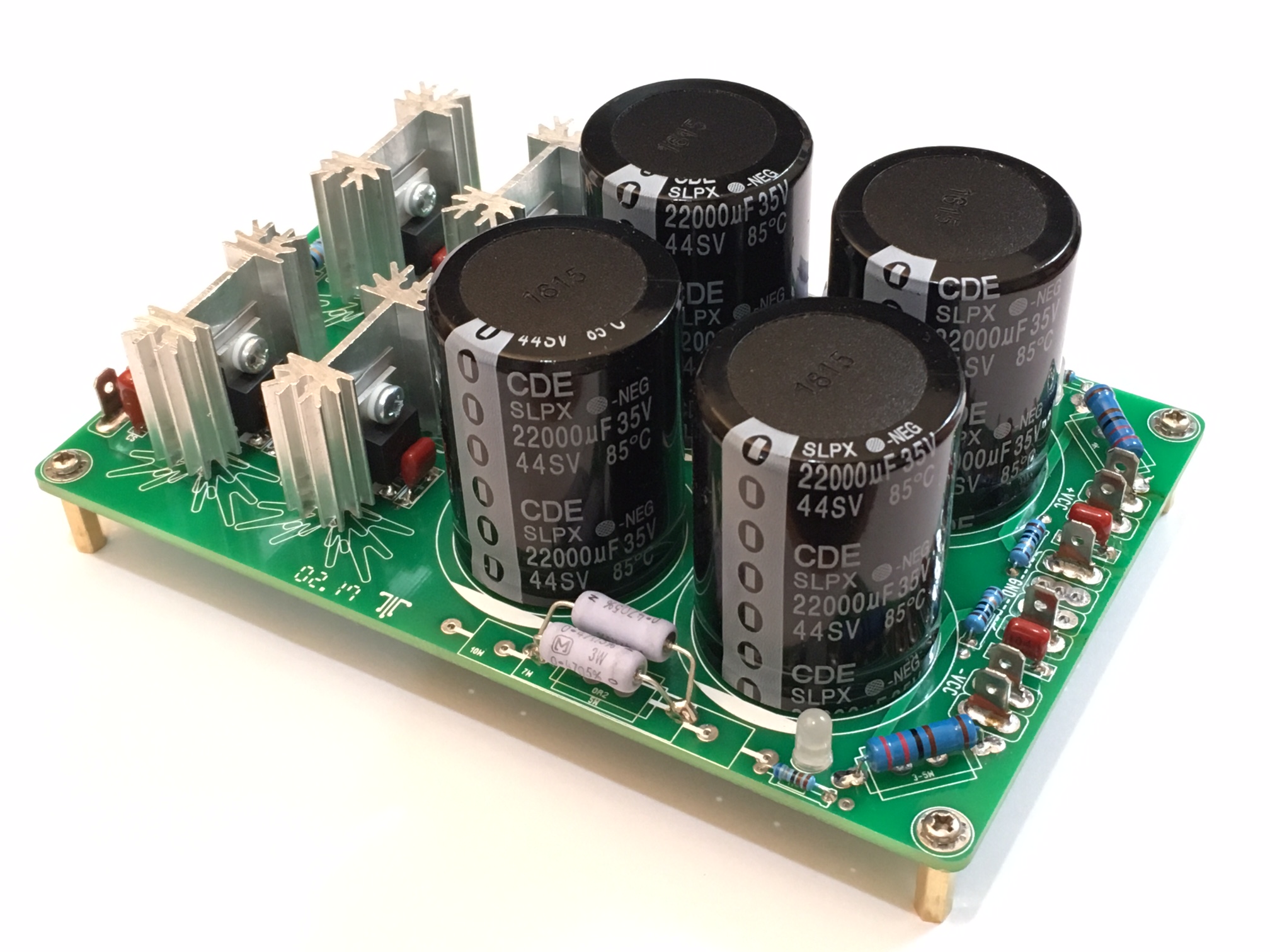
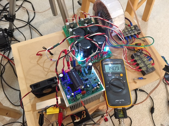
I just built a nicely laid out CRC board from this GB thread and used quality diodes resistors and caps from Mouser. The thing is beautiful but hooked it up to this setup and still getting the forest of noise. It must be trafo saturation?
http://www.diyaudio.com/forums/grou...er-supply-class-amplifier-27.html#post5050610
So I think P2P PSU's are just as good and I also think decent low noise SMPS can work well for Class A with a lot less radiated EMF.
http://www.diyaudio.com/forums/grou...er-supply-class-amplifier-27.html#post5050610
So I think P2P PSU's are just as good and I also think decent low noise SMPS can work well for Class A with a lot less radiated EMF.
hi,
iam planning on using single 600 va center tapped , dual bridge rectifier 35 A ,and two power supply pcb for stereo amp class ab(250 watts @ 4 ohm) as exactly in rod elliots diagram attached below with ground loop breaker , i just added couple of more caps for each amp , going by the discussion here is it not advisable
http://sound.whsites.net/p04_fig1.gif
another option i have is with ,single 50 amps diode bridge and connect pcb one after another totalling 4 caps each rail ( single psu), avoiding loop as in post 23 by mark
which wound be better
thank you
Nice board, i don't see any problems comming from there.I just built a nicely laid out CRC board from this GB thread and used quality diodes resistors and caps from Mouser. The thing is beautiful but hooked it up to this setup and still getting the forest of noise. It must be trafo saturation?
So I think P2P PSU's are just as good and I also think decent low noise SMPS can work well for Class A with a lot less radiated EMF.
Your amp has a transformer at the input, are you shure it isn't influenced by the magnetic field of the power transformer? Could explain the big 60Hz component in the noise.
Mona
I hope you didn't use the central mounting bolt, as it looks like that will ground the dirty end of the PSU.xrk971 said:I just built a nicely laid out CRC board from this GB thread
I hope you didn't use the central mounting bolt, as it looks like that will ground the dirty end of the PSU.
No, the board is only connected via a ground from clean end to the GLB on the terminal block, and of course +/- rails to each amp, and clean GND to each amp. Each amp is verified to not be in contact with chassis GND. Other end of GLB on terminal block connects to earth GND and chassis GND.
OK. Getting rid of hum/buzz is a matter of eliminating one potential cause after another. You now seem to have the grounding right so now look at other things: loop coupling, for example.
You still have parallel diodes and paths. If the return diodes, BR3/4 switch faster than the return diodes BR1/2 then the current will flow back via that pathway.
Ok, then can someone explain to me how does Mr Pass manages to make two dual-rail CRC's out of two secondary windings as shown here for F7? Should we be getting transformers with 48v output secondaries so that we can use them to make a +/-24v dual rail each?
From 6Moons review article.


I can see two secondaries feeding two bridges feeding two capacitors banks, although pictures are not the most useful way to analyse a circuit.
I can only see a positive and a negative rail connected to two amps. Where it is different is the short ground/0V connections and no fancy snubbers on the rectifiers like your new PSU has.
I can see two secondaries feeding two bridges feeding two capacitors banks, although pictures are not the most useful way to analyse a circuit.
The wires from the PSU board to the amps are obviously +/- rails. And since only a single rectifier is used, I suspect that the secondaries on the transformer are 34VAC, which when rectified makes 48v, and if center is referenced to 0v, then we get +/-24v from a single secondary. So maybe the way to do this in the future is to size a transformer for double the voltage in order to get two monoblock PSU's from a single trafo with two secondaries.
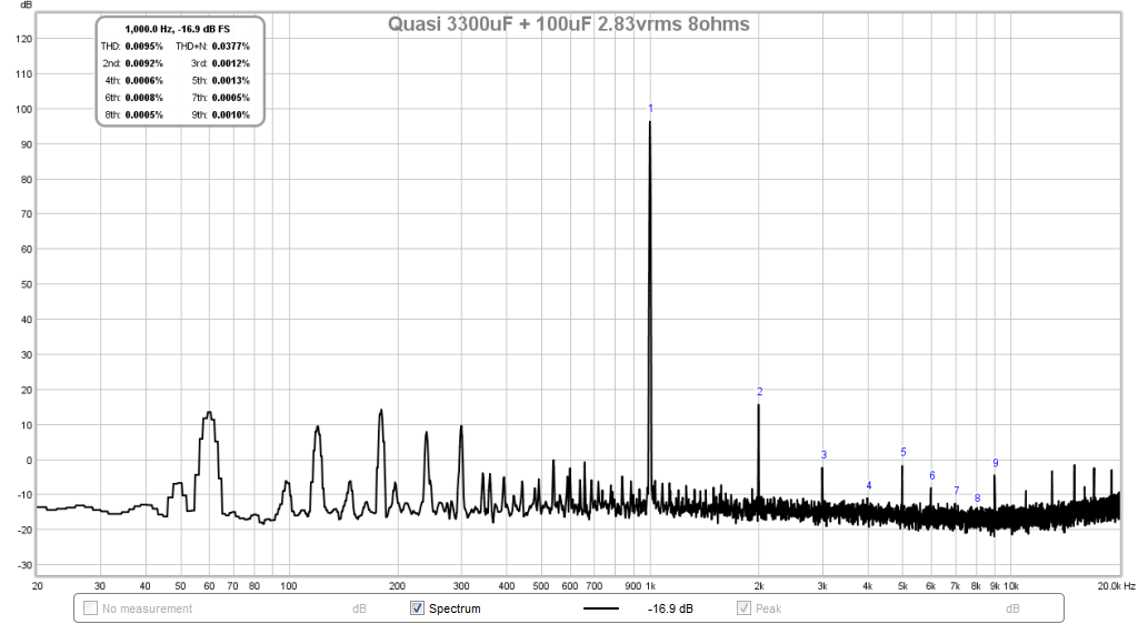
Btw, I tried my new CRC with a different brand of transformer (avel Lindberg 250VA 25vac) and different amp (Ranchu/Aksa Quasi) but using same PSU topology as shown in above post with clean ground from CRC gnd to GLB etc. and got a clean FFT no noise hash. Still has 60Hz adn 120Hz etc but its about -80dB so not audible.
Here is 2.83vac into 8ohm load driven through a 3300uF Panasonic FC and Elna Silmic II 100uF and Wima 1uF MKS in parallel (why? I was using as a headphone amp):
Attachments

Last edited:
- Status
- Not open for further replies.
- Home
- Amplifiers
- Power Supplies
- Strange Forest of Noise with Linear PSU