“dirty power”
Hello All,
I believe that there is way too much focus on this star or common grounding point.
Even if we have a single chassis stereo amplifier with two separate distinct power supplies or even two separate mono power supply amplifiers they will all tie together at a single common grounding point at the connection to the mains.
The issue of “dirty power” is even more global than the odd DIY power supplies we may build on our benches at home. I worked on the design of a Heart Cauterization Lab. We include a large KVA isolation transformer to protect the lab from the dirty power supplied from the hospital supply it was connected to. It turns out that the isolation transformer served better protecting the hospital systems from the power trash produced in the Cath Lab.
DT
The key compromise is the single star point (shown schematically as three separate junctions, but in reality should be one common junction).
Hello All,
I believe that there is way too much focus on this star or common grounding point.
Even if we have a single chassis stereo amplifier with two separate distinct power supplies or even two separate mono power supply amplifiers they will all tie together at a single common grounding point at the connection to the mains.
The issue of “dirty power” is even more global than the odd DIY power supplies we may build on our benches at home. I worked on the design of a Heart Cauterization Lab. We include a large KVA isolation transformer to protect the lab from the dirty power supplied from the hospital supply it was connected to. It turns out that the isolation transformer served better protecting the hospital systems from the power trash produced in the Cath Lab.
DT
I really like the ESP PSU. It manages to get as close to two monoblock PSU's from a CT transformer as possible................
as stated by Trobbins, the common zero volts actually achieves the OPPOSITE of getting close to two monoblocks.The key compromise is the single star point (shown schematically as three separate junctions, but in reality should be one common junction).
The common zero volts LOOKS LIKE separate supplies but is the half loop waiting for an error downstream that will create terrible hum/mains interference.
A single star point should be fine for most mono or stereo amps - just break any earth connections using the diode DC blocker. For stereo amp, one can have endless fun using high end soundcard noise floor and distortion testing looking at modulation and cross-channel interactions/seperation, and work out whether that is insignificant for source material such records, cd's, streaming, or end-of-line detection such as your ears in your normal ambient background whilst sitting in your custom anechoic chamber.
Ha ha, sounds like you've had "endless fun" chasing the noise floor and decided you have better things to do......
No I haven't done a suite of such tests - it would be interesting to do, and to rationalise the resulting measured performance. Just my gut feeling that if an amp has that grounding scheme, and it's done well, then it should be fine for most applications. Although I do have a vintage stereo about to go back on the bench now that some NOS 6GW8 have come in to use for reference.
Last edited:
It is not very close to two monobloc PSUs. Voltage drops in the transformer are common to both channels, so they are not isolated from each other. It forces you to join the two PSUs at the most dirty point possible. All in all, it gives the superficial appearance of separation while actually delivering almost no separation at all. The only real separation it has is that when all the rectifiers are switched off each amplifier channel has its own reservoir to drain down.xrk971 said:I really like the ESP PSU. It manages to get as close to two monoblock PSU's from a CT transformer as possible.
Would be interesting to see if it works without hum. ESP gives some advice here: Power Supply for Power Amplifiers
Imagine using this in a 2-way active system, where voltage drop and frequency per channel is not equal.
Imagine using this in a 2-way active system, where voltage drop and frequency per channel is not equal.
Last edited:
Imagine using this in a 2-way active system, where voltage drop and frequency per channel is not equal.
I've experimented with both, and separate supplies for the LF and HF amps is much easier to implement
I guess my desire was to get better stereo separation by having two CRC's and each going through their own bridge. Apart from everyone saying that the common 0v point is dirty (as in mains noise and hum), would not the ESP layout give better channel separation than both channels running off same CRC? I know that is bad for stereo cross talk without even measuring it as I can disconnect the input for one channel and still hear some sound (albeit much softer) coming out of the speaker with input disconnected.
I guess my desire was to get better stereo separation by having two CRC's and each going through their own bridge. Apart from everyone saying that the common 0v point is dirty (as in mains noise and hum), would not the ESP layout give better channel separation than both channels running off same CRC? I know that is bad for stereo cross talk without even measuring it as I can disconnect the input for one channel and still hear some sound (albeit much softer) coming out of the speaker with input disconnected.
Hello All,
The separate bridge rectifiers and CRC’s do provide greater separation than the nay sayers will allow. The separate capacitors are more than just reservoirs; they are filter capacitors that shunt higher frequencies to ground. Each of the separate power supplies has increased filtering with increasing frequency. For lower frequencies the separate power supplies are increasingly influenced by the voltage sag of the common transformer.
If you dig into Rod Elliot’s articles he speaks of the PSRR of the amplifiers powered by this dual power supply design. The amplifiers have good PSRR that decreases with increasing frequency. Rod opines that there is no need for voltage regulation.
Edit: Look at the Rane MA-6 and MA-6S. 6 amplifiers in one box, one transformer with better than decent separation.
DT
Last edited:
Hello All,
The separate bridge rectifiers and CRC’s do provide greater separation than the nay sayers will allow. The separate capacitors are more than just reservoirs; they are filter capacitors that shunt higher frequencies to ground. Each of the separate power supplies has increased filtering with increasing frequency. For lower frequencies the separate power supplies are increasingly influenced by the voltage sag of the common transformer.
If you dig into Rod Elliot’s articles he speaks of the PSRR of the amplifiers powered by this dual power supply design. The amplifiers have good PSRR that decreases with increasing frequency. Rod opines that there is no need for voltage regulation.
Edit: Look at the Rane MA-6 and MA-6S. 6 amplifiers in one box, one transformer with better than decent separation.
DT
I definitely will give this a try as it is simple rewiring at the terminal block. I had another amp (VHEX+) powered by a common 52v dual rail SMPS. I installed a 9.6mF/0.47R/9.6mF CRC in between the SMPS and each amp channel and the newfound stereo imaging and sound stage was remarkably improved. I did not have a measurement rig back then but would imagine stereo crosstalk probably increased by at least 20dB if not more. In my view, that was the single most cost-effective improvement in SQ for the relatively small cost of 8 x 9600uF 63v caps and 4 x 0.47R 5w power resistors.
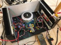
An update to this problem. I finally revised the PSU to use dual bridges per CRC, each bridge fed by a separate secondary winding on the trafo. Each amp channel shares a secondary winding for one of the rails. So basically, each secondary output winding feeds two bridges (one left and one right). This seems to have quieted the forest of noise in the FFT's a lot. I am still seeing a lot of 60Hz/120Hz/180Hz and hearing hum when ear is 3in from woofer. Fluke measures 1.2mV AC on the speaker out for right channel and 2.2mV on the left channel. The setup provides excellent stereo separation as I can disconnect one channel and press my ear against the other channel and not hear anything. Whereas when the channels shared a common PSU CRC, I could hear the crosstalk easily.
Here is photo of new setup. Note that I am using a GLB and placing clean ground on one side and dirty ground (earth, chassis, trafo static screen) on other side.

The amp is running 1.3amps bias and measured 120vac current from wall is 1.1amp. This is a 400VA trafo and I hear a slight hum from it, and there is an occasional "crackling" sound. Very strange. Is this because it is saturated?
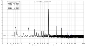
Here is FFT with 2.83v into 8ohm resistor load:

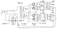
Here is schematic of setup, amp board ground connects to CRC ground points:

Here is photo of new setup. Note that I am using a GLB and placing clean ground on one side and dirty ground (earth, chassis, trafo static screen) on other side.
The amp is running 1.3amps bias and measured 120vac current from wall is 1.1amp. This is a 400VA trafo and I hear a slight hum from it, and there is an occasional "crackling" sound. Very strange. Is this because it is saturated?
Here is FFT with 2.83v into 8ohm resistor load:
Here is schematic of setup, amp board ground connects to CRC ground points:
Attachments
Last edited:
Having one secondary feeding two bridges means that you have lost control of where the currents go. The return current from a charging pulse could go directly to the cap junction or via the other half of the supply and the 'clean ground' wires. This is why you still have hum. You cannot have two things both isolated and connected.
Since you are using separate bridges for each secondary I think it's better to create the 0V rail at the output?
Yes, given the perverse design one could still improve things a little by directly joining the two 0V outputs, then running a single wire from there to the groundbreaker. This would shorten the piece of wire with uncontrolled charging pulses in it.
The funny thing about PSUs is that many people seem to instinctively wire them incorrectly, even after having the principles patiently explained to them.
The funny thing about PSUs is that many people seem to instinctively wire them incorrectly, even after having the principles patiently explained to them.
You have a "clean ground", then you go and connect the amps to two locations that a not "clean". There is alway going to be a voltage between these two grounds. And, the voltage between the amps will increase as the length of the ground leads to the amps increases.
Move the two PSU together, grounds connected by a thick wire or bar, then connect the amp grounds with short leads and the GBL to this midpoint.
Don't run any of the audio, DC or grounds along the AC wiring.
Move the two PSU together, grounds connected by a thick wire or bar, then connect the amp grounds with short leads and the GBL to this midpoint.
Don't run any of the audio, DC or grounds along the AC wiring.
Last edited:
Having one secondary feeding two bridges means that you have lost control of where the currents go. The return current from a charging pulse could go directly to the cap junction or via the other half of the supply and the 'clean ground' wires. This is why you still have hum. You cannot have two things both isolated and connected.
I am not seeing why what I am doing is so egregiously wrong as it follows the ESP topology of driving two bridges in parallel with one winding. I just added an extra set of bridges.
An externally hosted image should be here but it was not working when we last tested it.
So your detailed technical explanation as to why it works is "it must be OK because someone else did it"? You have taken a poor design from ESP, then made it worse by adding extra bridges and poor grounding. ESP is normally reliable, but on this point he is wrong.xrk971 said:I am not seeing why what I am doing is so egregiously wrong as it follows the ESP topology of driving two bridges in parallel with one winding. I just added an extra set of bridges.
The basic problem, as I keep saying, is that you don't know where the currents go so you can't control them. When the bridges switch on at the AC peak, which particular diodes switch on first? Even after all the relevant ones are conducting, how do they share current between them? How much current takes the short path and how much takes the long path via the other half of the PSU? To the extent that any current takes the long path you have different ground references for the two channels - yet almost certainly elsewhere in your system these two different 'grounds' will be connected together and treated as though they are at the same potential.
You have three choices:
1. work it out yourself and understand what we are saying
2. simply believe us
3. put up with some hum
![FSCN3809[1].JPG](/community/data/attachments/577/577335-adb21f48e05c7af18e5efe7641502330.jpg?hash=rbIfSOBcev)
- Status
- Not open for further replies.
- Home
- Amplifiers
- Power Supplies
- Strange Forest of Noise with Linear PSU