It looks like you haven't used a bridge rectifier in your GLB as shown in the ESP pages. This is required for safety under fault conditions
Which dirty GND is connected to the chassis? If both you have connected the two halves at both ends (clean and dirty). If just one you have now ensured that your audio ground is dirty. Nothing whatsoever should be connected to the dirty end of a PSU. It is not surprising that the problem still remains.xrk971 said:I rebuilt my PSU just like the diagram above except with just 33mF on each side of the R in the CRC and connected the clean GND together, dirty GND is connected to EARTH GND
Show us a circuit diagram of what you have done, not a photograph.
If you look closely at the transformer you will see that the CT is actually the joining of the two secondary windings.I was trying to make two separate 24v dual rail supplies from a single CT transformer. Is that not possible then?
So to do this supply as dual mono would require two CT transformed?
An externally hosted image should be here but it was not working when we last tested it.
With care, you can separate this common connection, add an extra wire and end up with two separate secondaries, which is what you want.
Now you can end up with supplies as per you diagram.
The two supplies can now be commoned at the load end of your circuit and you are good to go.
Dan.
He has already done this. We are now trying to get him to do the commoning at the load end only.
He has already done this. We are now trying to get him to do the commoning at the load end only.
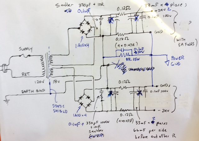
Here is the modified PSU schematic. I believe I incorporated all suggestions from folks:
1. Two separate full wave bridges (they are very compact P2P jobbies at the back of the CRC stacked on top of one another - two diode rings 8 pieces total. Hard to see without closeup, but yes there are two full wave bridges.)
2. Dirty ground to chassis isolated from clean power ground with 8R(25w) and 0.1uF 250v film GLB (I have 10R but it's kind of big white cement filled one that doesn't quite fit in that space so figured 8R is close enough). This GLB is similar to the one suggested on the ESP website.
3. Power ground tied together at clean end of CRC and uses star topology from that point out to each amp.
I wonder if the problem may be the brass standoffs and screws that mount PCB are connected to board's (clean) ground? Need to check to see if Teabag's layout does this. If so will have to switch to nylon standoffs.
Attachments

Last edited:
You need to remove the two connections from the dirty ground end of the PSU. Any ground connection to anything else, via GLB or not, must come from the clean end only. We keep telling you this but you seem reluctant to take it seriously.
Be aware that the white cement filled resistors have poor overload capability. If shorted across the mains they could fail or explode before the breaker trips.
If the circuit boards have separate connections to chassis then these need to be removed as well. Grounding needs to be designed, by thinking about where the currents go. Once you understand it you will find that it is not difficult to get near-zero hum and buzz.
The schematic shows a completely different setup than the last photo you posted.
The photo has 4 diodes and the transformer is configured CT. The schematic has 8 diodes and transformer balanced.
Draw what you have built, add amp and source grounds as well.
The photo has 4 diodes and the transformer is configured CT. The schematic has 8 diodes and transformer balanced.
Draw what you have built, add amp and source grounds as well.
My mistake - I missed the fact that CRC ground is only connected to clean side. Will also check PCB standoffs for inadvertent ground connection to chassis. Will have to wait until late tonight though.
Thanks for all your help. Hopefully will get to the bottom of this.
Thanks for all your help. Hopefully will get to the bottom of this.
The schematic shows a completely different setup than the last photo you posted.
The photo has 4 diodes and the transformer is configured CT. The schematic has 8 diodes and transformer balanced.
Draw what you have built, add amp and source grounds as well.
I have said this before - there are 8 diodes forming two separate full wav bridges there - you must not believe what I say.
The schematic is drawn correctly except for inadvertent dirty to clean ground connection on CRC. Doesn't matter anyway until I remove the dirty ground connection to the CRC completely as DF96 suggests.
Here is closeup of the two bridges. You can see two bridges lying on top of one another.
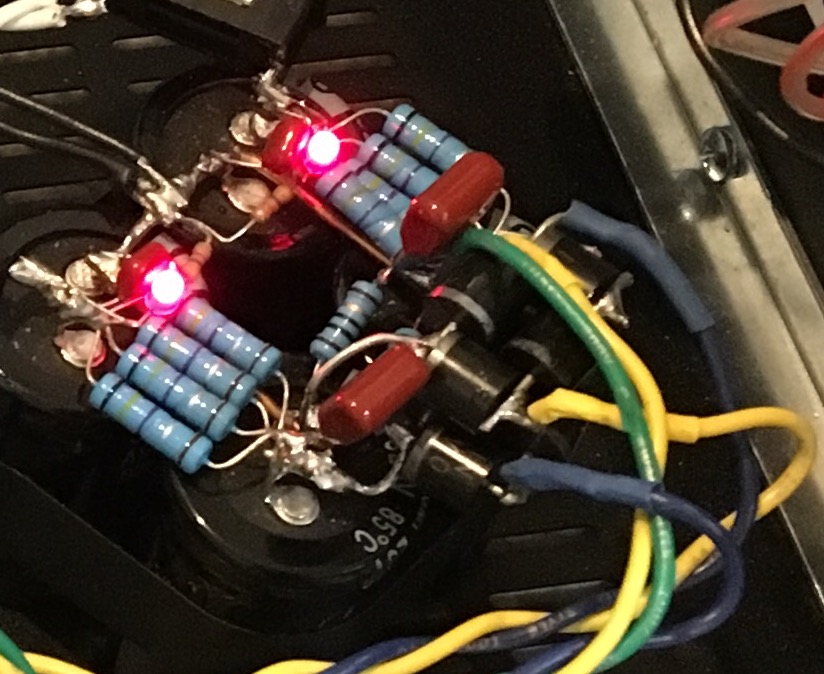
Note that there are two sets of yellow and blue wires. Each goes to one independent secondary winding.
And I said I am not using white cement resistor. It's the 25w gold anodized heatsinked one in lower right corner of earlier photo.
Attachments
Last edited:
You want ONE effective (busbar) common ground point, ie cabinet, PE, transformer shield, DC supply earth common and input grounds all low impedence connected to ONE low impedance conductor/plane.The schematic is drawn correctly except for inadvertent dirty to clean ground connection on CRC. Doesn't matter anyway until I remove the dirty ground connection to the CRC completely as DF96 suggests.
Dan.
I'm still concerned you haven't used a bridge in the GLB as shown in the ESP pages
An externally hosted image should be here but it was not working when we last tested it.
Ah - sorry it was late last night. Missed that. Never saw a bridge all by itself between earth and ground. Can't I just use two diodes in opposite polarity connected ? We do this all the time at the PCB level with 10R ground lift resistors and two diodes.
Looks like I have a bunch more corrections to the circuit to make this right. Will try again later tonight.
Yes, a bridge is generally used because they are nicely packaged high current diodes
Another important factor is what else is there connected to the zero volt line and in what physical relation? If there is any power supply connection in different places, you can get this issue.
Also, where do you ground the test equipment? You may or may not measure something that is not part of the actual signal - sometimes you do get lucky ;-)
Look carefully at the FFT - there's a lot of info in it. What you have is clearly rectified mains - I can see you are in a 60Hz country, and all those harmonics of the 60Hz point to a supply ground loop or common ground with signal. Unlikely to change with isolating the PE.
The source is the rectified voltage. If you look at your cap after the rectifier you see something that resembles a saw tooth shaped voltage. And Fourier told us that a sawtooth shape has the fundamental and all even harmonics. So when this voltage shape gets into the amp through the power supply lines, or flows through a wire that has non-zero impedance, you get such a noise voltage. The former possibility is normally quite low because the amp PSRR is normally quite high at low frequencies. That's why I would bet on wiring issues.
The other clear giveaway is that it is much lower with the SMPS's substituted!
And finally, when you disconnected the earth connection, the HF hash got much lower, but the mains harmonics remained as they were.
All of that from your 1st post.
Jan
Last edited:
Thank you, Jan Didden for your comments from single post 1 study.
Another important factor is what else is there connected to the zero volt line and in what physical relation? If there is any power supply connection in different places, you can get this issue.
For the FFT, I was using a Focusrite Solo 2G USB audio interface (which I know from measurements of my battery powered amps is quite clean and has -126dB noise floor.) It has signal ground connected to amp speaker output ground on amp PCB. I disconnect the laptop wall plug when doing measurements to remove any 60Hz contribution (about -115dB at 60Hz) from laptop mains.
Also, where do you ground the test equipment? You may or may not measure something that is not part of the actual signal - sometimes you do get lucky ;-)
When doing FFT, at amp speaker output ground as mentioned above.
When measuring voltage across CRC rails, at local GND at CRC filter.
Look carefully at the FFT - there's a lot of info in it. What you have is clearly rectified mains - I can see you are in a 60Hz country, and all those harmonics of the 60Hz point to a supply ground loop or common ground with signal. Unlikely to change with isolating the PE.
PE=power earth? I think you are right, my problem is that there are multiple, happenstance ground paths. I need to design the ground paths rather than let them be arbitrary. This would not bother me had I never looked at FFT - you can't really hear it except for very slight hum.
The source is the rectified voltage. If you look at your cap after the rectifier you see something that resembles a saw tooth shaped voltage. And Fourier told us that a sawtooth shape has the fundamental and all even harmonics. So when this voltage shape gets into the amp through the power supply lines, or flows through a wire that has non-zero impedance, you get such a noise voltage. The former possibility is normally quite low because the amp PSRR is normally quite high at low frequencies. That's why I would bet on wiring issues.
The other clear giveaway is that it is much lower with the SMPS's substituted!
And finally, when you disconnected the earth connection, the HF hash got much lower, but the mains harmonics remained as they were.
So it's all really about ground loops - which cause more than hum - but let in all those HF harmonics. What puzzles me is why moving the input leads physical location changes the HF hash? Yet when I shorted the input with a jumper across +/- input at terminal block - the hash was still there?
All of that from your 1st post.
Jan
And Fourier told us that a sawtooth shape has the fundamental and all even harmonics.
If I may just clarify the wording there Jan, because it could be interpreted differently. The fundamental here refers to 120Hz as produced by the bridge rectifier and not the mains frequency fundamental of 60Hz which will not be present in the ripple component.
But the noise spectum shows a big 60Hz peak ! If it isn't from a hum source in the amp it is from the bridge rectifier.If I may just clarify the wording there Jan, because it could be interpreted differently. The fundamental here refers to 120Hz as produced by the bridge rectifier and not the mains frequency fundamental of 60Hz which will not be present in the ripple component.
Mona
- Status
- Not open for further replies.
- Home
- Amplifiers
- Power Supplies
- Strange Forest of Noise with Linear PSU