Its difficult to advise from diagrams and pictures because there is so much more going on in the real amp.
Have you tried disconnecting the AC to one of the bridges and running just one channel in isolation. Make sure that is hum free first.
Have you tried disconnecting the AC to one of the bridges and running just one channel in isolation. Make sure that is hum free first.
The problem is that a small amount of the charging current returns via the other paths.
Exactly !
The problem with grounding is that its easier if you just think it all through, rather than trying to follow some generic instructions. The link I posted a little earlier gives some good background on a real practical example of something that should have been faultless, and that in reality wasn't.
Separate supplies are better, but a single should be perfectly acceptable as witnessed by all the commercial amps out there. Singles are just more tricky to get right and to avoid hum and channel interactions.
Thank you for this Mark_Whitney:

Looks like a single supply should solve the ground loop hum problem. Removing the gnd from CT should reduce some of the noise - as I observed when disconnecting the Earth safety ground. But what causes all the other lower (below 1kHz) noise?
Start with one side first and one CRC only. Will give that a try.
This grounding scheme is a lot trickier than I thought - at least to do it properly.
OK.xrk971 said:Here is what I did
Problems:
1. Two 'separate' PSUs joined at the dirty end.
2. Two 'separate' PSUs joined by common secondaries.
3. The dirty end join then connected to safety ground.
You cannot have "isolation" while at the same time joining things together. With a pair of secondaries wired as one secondary with a CT you can only drive one bipolar PSU, using one bridge. Alternatively, use them as separate secondaries each feeding its own bridge to form the two halves of one bipolar PSU.
Let me rewire as single PSU with two halves each with its own secondary - much like the Pass F1 power supply. Shall see if noise goes away.
Better, but you should join the two halves together at the clean end (which you have called 'GND') not the dirty end.
On a separate issue, if you feel snubbers are needed they should be across the secondaries not the reservoir caps. 'Bypass' caps should be at the audio circuit end, not just slapped across a smoothing cap.
On a separate issue, if you feel snubbers are needed they should be across the secondaries not the reservoir caps. 'Bypass' caps should be at the audio circuit end, not just slapped across a smoothing cap.
Run a short thick wire between the two amp boards (0V) and connect the PSU 0V and chassis ground to the midpoint of this wire. Also, replace the ground to chassis connection with a GLB. But only if you have lifted the input ground from the power ground.
Last edited:
The analogy of current flow to water flow I find useful when visualizing ground loop currents, trying to keep a smooth one way, balanced flow like making connections at midpoints and having very low impedance paths.
Run a short thick wire between the two amp boards (0V) and connect the PSU 0V and chassis ground to the midpoint of this wire. Also, replace the ground to chassis connection with a GLB. But only if you have lifted the input ground from the power ground.
Are you saying do this to my original bad circuit or the new one that will use one CRC? What's a GLB?
I know Pass has several CL06 thermistors in his PSU.
So let me ask this: if I had a common bridge to one CRC then from there, split off to two independent capacitance multipliers, would that effectively serve to decouple the left and right channels with a high level of isolation so that they will be like monoblocks?
GLB= Ground Loop Breaker. Have a look at this page Earthing (Grounding) Your Hi-Fi - Tricks and Techniques
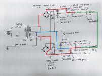
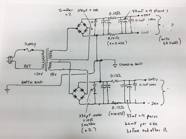
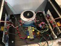
I rebuilt my PSU just like the diagram above except with just 33mF on each side of the R in the CRC and connected the clean GND together, dirty GND is connected to EARTH GND with a GLB consisting of an 8R 25w resistor paralleled with a 100nF 250v film cap. The two secondaries are separate and connected to two separate bridges as shown.
Here is photo of new setup (wire connections on terminal block from top is as follows: secondary 1+, secondary 1-, secondary 2+, secondary 2-, clean GND to GLB, dirty GND/Chassis GND/EARTH/Trafo static shield, mains hot, mains neutral):

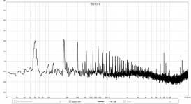
Here is FFT of amp output with no signal before the change to the PSU:

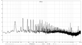
Here is after switching to the new setup as described above - seems that the noise is still there:

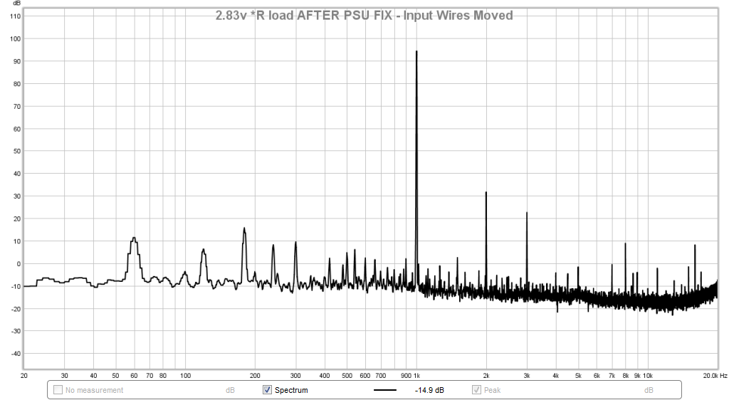
Here is with 2.83v into 8 ohms 2kHz signal:
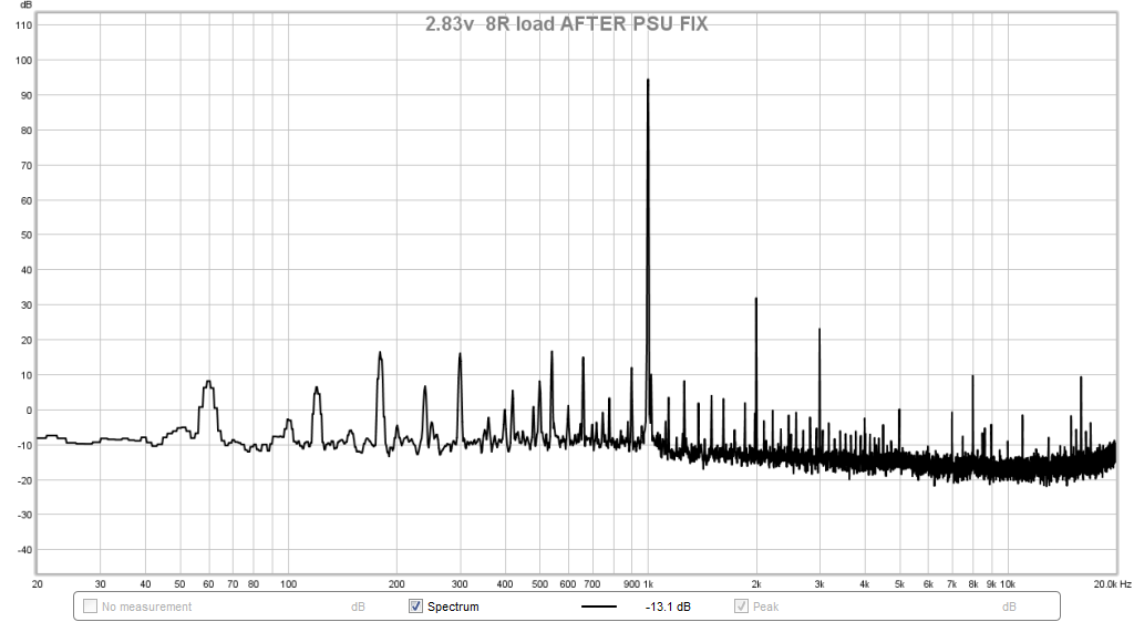
But now I find that moving the input cables high up (away from mains input) gets the HF hash to really go down. I still hear a little bit of hum. So really not much better than my "dual mono" PSU that I had before.
8v into 8R load with input wires moved up high away from mains inputs:
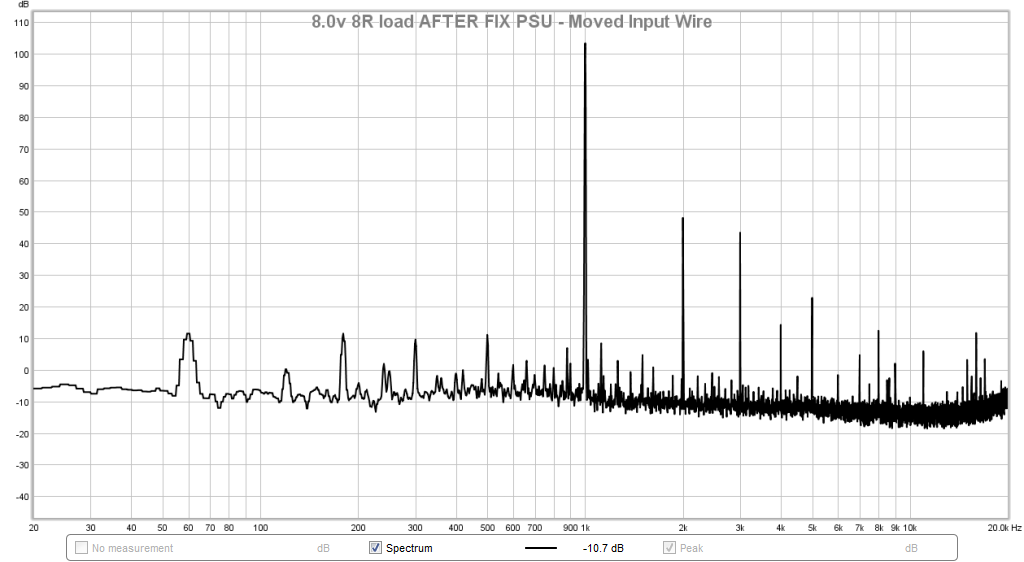
So maybe it is the whole saturation thing that causes the 3rd harmonic and odds above that? Mains measure in at 123.0vac.
I think the PSU topology is now setup correctly per recommendations of folks on this thread. The slight hum I hear is intrinsic to this design? Pass' Specs for M2 noise is 600uV with inputs shorted.
Here is photo of new setup (wire connections on terminal block from top is as follows: secondary 1+, secondary 1-, secondary 2+, secondary 2-, clean GND to GLB, dirty GND/Chassis GND/EARTH/Trafo static shield, mains hot, mains neutral):
Here is FFT of amp output with no signal before the change to the PSU:
Here is after switching to the new setup as described above - seems that the noise is still there:
Here is with 2.83v into 8 ohms 2kHz signal:
But now I find that moving the input cables high up (away from mains input) gets the HF hash to really go down. I still hear a little bit of hum. So really not much better than my "dual mono" PSU that I had before.
8v into 8R load with input wires moved up high away from mains inputs:
So maybe it is the whole saturation thing that causes the 3rd harmonic and odds above that? Mains measure in at 123.0vac.
I think the PSU topology is now setup correctly per recommendations of folks on this thread. The slight hum I hear is intrinsic to this design? Pass' Specs for M2 noise is 600uV with inputs shorted.
Attachments


Last edited:
So let me ask this: if I had a common bridge to one CRC then from there, split off to two independent capacitance multipliers, would that effectively serve to decouple the left and right channels with a high level of isolation so that they will be like monoblocks?
No, there is no ground isolation. To build monoblocks you need four secondaries from either one or two transformers.
Does the amount of hum change when you unplug the amp from the mains? The amps should play for a while without mains power connected.
It may help if you move the chassis connection to the clean GND and shorten the power/GND leads to the amps. The long PE/GND leads connected to the chassis are also not helping things.
When a transformer saturates the magnetic flux is no longer contained in the core. This will induce voltage in surrounding parts. So adding filter capacitance really doesn't reduce this radiated noise.
If the noise comes from other transformers on the same AC power line then capacitors will filter it as the stray magnetic field is only local to the saturated core.
If you use a buck transformer to reduce the mains voltage it will not significantly lower the rail voltage.
So odd order harmonics come from saturation and are inserted into the surrounding leads by magnetic flux. Rectifier distortion comes from turn on and turn off surges and has even order harmonics. These can be treated by inductors and or capacitors.
If you don't want to use a buck transformer then you need to isolate the power transformer so the flux leakage doesn't make it to the circuitry.
- Status
- Not open for further replies.
- Home
- Amplifiers
- Power Supplies
- Strange Forest of Noise with Linear PSU