When a transformer saturates the magnetic flux is no longer contained in the core. This will induce voltage in surrounding parts. So adding filter capacitance really doesn't reduce this radiated noise.
If the noise comes from other transformers on the same AC power line then capacitors will filter it as the stray magnetic field is only local to the saturated core.
If you use a buck transformer to reduce the mains voltage it will not significantly lower the rail voltage.
So odd order harmonics come from saturation and are inserted into the surrounding leads by magnetic flux. Rectifier distortion comes from turn on and turn off surges and has even order harmonics. These can be treated by inductors and or capacitors.
If you don't want to use a buck transformer then you need to isolate the power transformer so the flux leakage doesn't make it to the circuitry.
I has similar problem in the past with Class A amplifier and I can confirm that Simon is 100% right.
Magnetic field almost can not be shielded. (this one is very strong because
amplifier working in class A). Distance is only cure.
Even silicon steel around transformer reducing it very small.
Easyest way to confirm problem is long wires and removing transformer from box, measuring FFT simultaneuosly.
Or just rotating transformer....
If the saturation is the problem, would a larger higher VA rating one fix it, or is this a case of the transformer being designed for 110VAC and my mains are 123VAC?
This is a 400VA transformer (fairly hefty size) and Antek even says it can be used safely about 10% above rated capacity. Amps are running 1.25 DC amps (I measured with both voltage drop on sense resistors and with clamp on probe on mains - same value). That's 60w per channel (48v x 1.25amps) or 120w. Trafo is 400w rated so I am using it well below rated capacity.
Almost sounds like easiest fix is to use the two $19 SMPS bricks 🙂
https://www.amazon.com/gp/product/B00LUIKY4S/
Which, to me seems like such an easier way to run the typical +/-24v 1.25amp Pass Class A amps. Why bother with all this heavy iron and stray emissions? If I don't get rid of the ground loops and hash, I will just stop using big trafos. Not worth it.
But the noise spectum shows a big 60Hz peak ! If it isn't from a hum source in the amp it is from the bridge rectifier.
Mona
Granted, an open diode in the bridge would allow the mains frequency fundamental through. Its just not very likely though (my feeling 🙂)
If the saturation is the problem, would a larger higher VA rating one fix it, or is this a case of the transformer being designed for 110VAC and my mains are 123VAC?
This is a 400VA transformer (fairly hefty size) and Antek even says it can be used safely about 10% above rated capacity. Amps are running 1.25 DC amps (I measured with both voltage drop on sense resistors and with clamp on probe on mains - same value). That's 60w per channel (48v x 1.25amps) or 120w. Trafo is 400w rated so I am using it well below rated capacity.
Almost sounds like easiest fix is to use the two $19 SMPS bricks 🙂
https://www.amazon.com/gp/product/B00LUIKY4S/
Which, to me seems like such an easier way to run the typical +/-24v 1.25amp Pass Class A amps. Why bother with all this heavy iron and stray emissions? If I don't get rid of the ground loops and hash, I will just stop using big trafos. Not worth it.
It has nothing to do with transformer size. Using a transformer at 60 Hz rather than 50 Hz does decrease the time for saturation and does give a greater VA rating. A larger transformer will still saturate. Easy test is to use a buck transformer. You only need one rated at 4 Amps 12 Volts.
Have a look at how the diodes are mounted 😱Granted, an open diode in the bridge would allow the mains frequency fundamental through. Its just not very likely though (my feeling 🙂)
Mona
Attachments


Have a look at how the diodes are mounted 😱
Mona
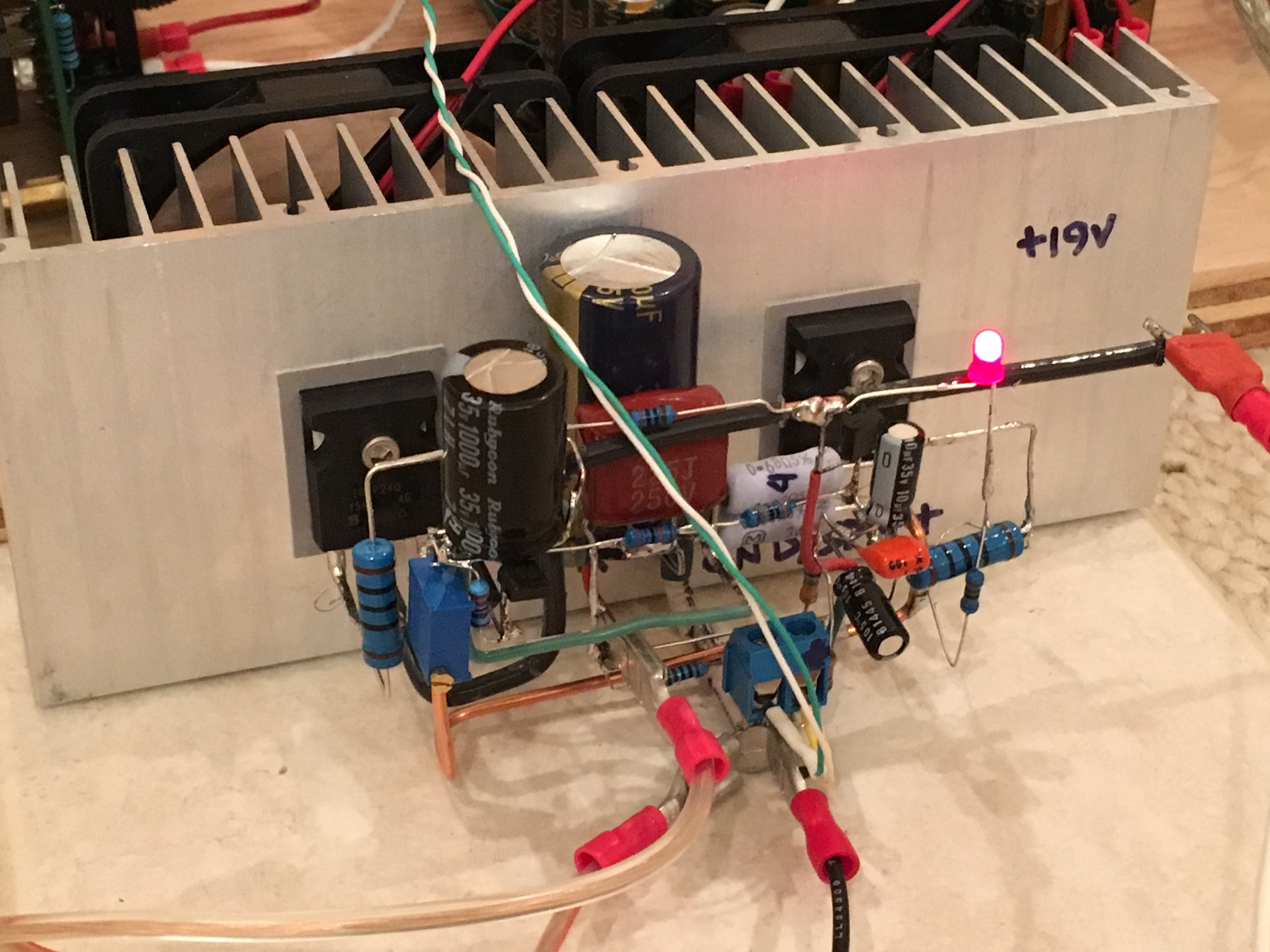
3D P2P looks strange but is the fastest and most compact way to make something simple with no PCB. Trust me, the connections are secure as the leads on those 1A10 diodes are very stout. Two square rings resting on top of one another with risers (pins bent 90deg down).
The voltages do indeed measure symmetrically at +/-24.3v
If that bothers you, here is my ACA in 3D P2P:
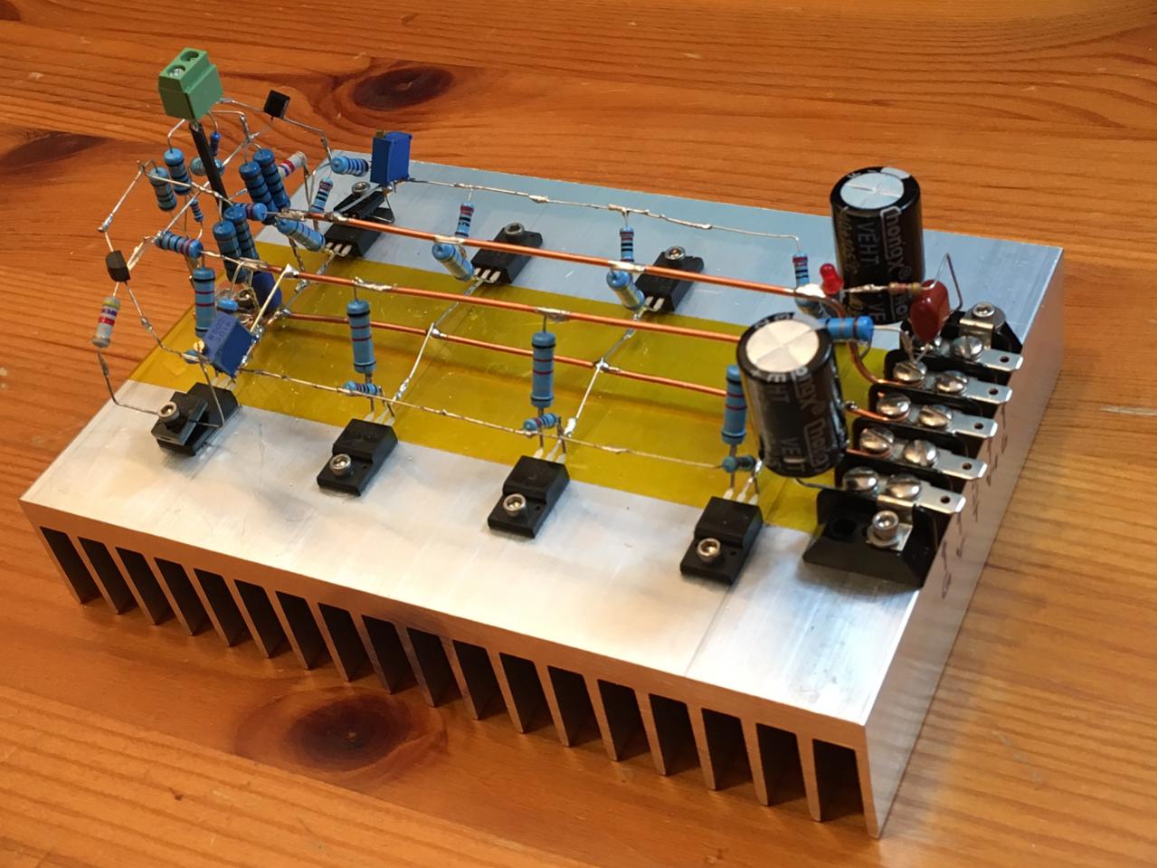
And an F5 with 2SK2013/2SJ313's:
Last edited:
Have a look at how the diodes are mounted 😱
Mona
It is very difficult working off photos. Why are there 5 diodes I wonder.
The hand wired examples shown have large loop areas not what is really needed, a PCB is a far better solution especially if you want to be in control of signal integrity/EMC...
It is very difficult working off photos. Why are there 5 diodes I wonder.
I'll take a better photo later. It's two square rings formed by four (4) 1A10 diodes each. One ring lying above the other - because I modified the existing one so easiest thing was to put another one on top. The top ring is slightly staggered to one side to allow the up/down interconnect legs to line up. 😛
The hand wired examples shown have large loop areas not what is really needed, a PCB is a far better solution especially if you want to be in control of signal integrity/EMC...
Agreed but it sure looks cool and was fun (and fast) to build. If I want ultimate low noise low stray RF pickup etc I would make it all SMT and as tight as possible with a ground plane. Here, my pocket single ended class A amp achieves really quiet noise performance.

Last edited:
Why don't you listen to Simon?
First check if your transformer does not saturate; Simon suggested how to do this.
When toroidal power supply transformers saturate, they do it quite agressively; that's their main drawback.
Often manufacturers design for high core excitation in order to maximize economics; then you have trouble in case of high line voltage.
Long time ago I had toroidals wound with 1 T of core excitation, also supplied with electrostatic screens.
Never problems with those (even lower strayfields this way).
So check your transformer first; everything else comes next.
Why don't you listen to Simon?
First check if your transformer does not saturate; Simon suggested how to do this.
When toroidal power supply transformers saturate, they do it quite agressively; that's their main drawback.
Often manufacturers design for high core excitation in order to maximize economics; then you have trouble in case of high line voltage.
Long time ago I had toroidals wound with 1 T of core excitation, also supplied with electrostatic screens.
Never problems with those (even lower strayfields this way).
So check your transformer first; everything else comes next.
That was next - and I believe what he suggested was to move trafo away from rest of amp case and use long flying leads. Can do that but is a major PITA so trying lower hanging fruit first. If that is the case, it would be really sad because I have this nice big $207 case and a $55 toroidal trafo that was supposed to go inside it, not out!
Are you sure that the transformer does not saturate?
When not, check that first.
When it saturates you can place the transformer a mile away but it will not help.
It should be no problem to place a well functioning transformer inside the case.
When not, check that first.
When it saturates you can place the transformer a mile away but it will not help.
It should be no problem to place a well functioning transformer inside the case.
If I may just clarify the wording there Jan, because it could be interpreted differently. The fundamental here refers to 120Hz as produced by the bridge rectifier and not the mains frequency fundamental of 60Hz which will not be present in the ripple component.
Good point indeed. Was it a double-phase rectifier?
Jan
Are you sure that the transformer does not saturate?
When not, check that first.
When it saturates you can place the transformer a mile away but it will not help.
It should be no problem to place a well functioning transformer inside the case.
Pieter, if the xformer is rated for the correct mains voltage and is not loaded excessively, could it then still saturate? It seems that saturation would point to a completely unsuitable transformer (assuming it is not broken) and that doesn't seem to be the case here.
And IF it is saturation, does it then create that slew of strong higher order even harmonics? Harmonics on the mains are mostly odd (because of the flat top).
I am still betting on wiring and/or grounding issues with signal ground and/or measurement ground. Occams Razor. It fits the bill (except that strong 60Hz, but I may be missing an obvious explanation here).
Jan
Last edited:
Pieter, if the xformer is rated for the correct mains voltage and is not loaded excessively, could it then still saturate? It seems that saturation would point to a completely unsuitable transformer (assuming it is not broken) and that doesn't seem to be the case here.
And IF it is saturation, does it then create that slew of strong higher order even harmonics? Harmonics on the mains are mostly odd (because of the flat top).
I am still betting on wiring and/or grounding issues with signal ground and/or measurement ground. Occams Razor. It fits the bill (except that strong 60Hz, but I may be missing an obvious explanation here).
Jan
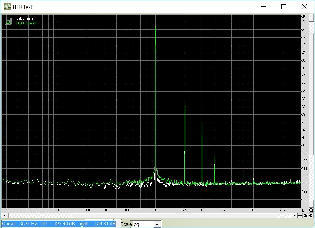
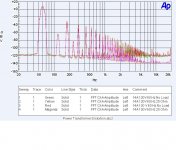
Virtually all transformers are designed to just run into saturation. It improves their regulation. The particular transformer is a cheap design and rated for 115 volts and is being used above that. Attached is what transformer saturation looks like using the cleanest transformer in my tests. It has a 220 volt primary and is fed from an amplifier producing less than .05% distortion. All odd order harmonics. The rectifiers would cause even order harmonics.
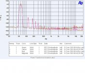
The second plot is a more typical transformer. compare that to the first post's plot.
Attachments
Last edited:
Pieter, if the xformer is rated for the correct mains voltage and is not loaded excessively, could it then still saturate? It seems that saturation would point to a completely unsuitable transformer (assuming it is not broken) and that doesn't seem to be the case here.
Using the transformer at the correct mains voltage does not seem to be the case here.
When so, yes it probably saturates.
Simon hinted at saturation based on the distortion spectrum.
What is so difficult in checking this before looking further?
Using the transformer at the correct mains voltage does not seem to be the case here.
When so, yes it probably saturates.
Simon hinted at saturation based on the distortion spectrum.
What is so difficult in checking this before looking further?
Oh no, I'm not saying not to check it, not at all. If that is easy to do, by all means!
- Status
- Not open for further replies.
- Home
- Amplifiers
- Power Supplies
- Strange Forest of Noise with Linear PSU