ya ya ya thanks costis_n it is very clear, but will you tell me one thing! Which is very important is that will it possible to use a 150ma 300-0-300V transformer in a KT88 or 6550 because i am not sure will it operate in low power dissipation e.g. 6-8W ? with a OPT 20W?
cause my old amp is a 6.7W EL34B. I am trying to upgrade or improve it.
cause my old amp is a 6.7W EL34B. I am trying to upgrade or improve it.
OK really thanks, but i still not one thing to ask: is the design of that amp ,
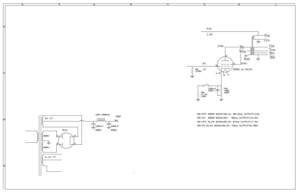
(EL34B) cathode is a // 390-400ohms and 100uF,63V turns out the voltage at 26.9V 67ma
and the schematic tells it can also replace with 6550 = KT88 and with a cathode bias 36.2V, 90.5ma .
So is the design really can interchange EL34 & KT88? With no bias problem!
(EL34B) cathode is a // 390-400ohms and 100uF,63V turns out the voltage at 26.9V 67ma
and the schematic tells it can also replace with 6550 = KT88 and with a cathode bias 36.2V, 90.5ma .
So is the design really can interchange EL34 & KT88? With no bias problem!
Hi,
Sorry missed this thread due to work. costis is right - there will be a voltage drop due to DC as the primary resistance of the transformer has to be taken into account. For eg. I use the UBT 2 OPT which has a primary DC resistance of 430 Ohms and drops about 20 Volts at a plate current of 70mA. Also, the mains transformer needs more power. With more than 70mA per channel for the KT-88 alone it would be over loaded. We need to consider around 30 ma for the 2 driver tubes plus some allowance. Reg. the last point 90mA bias for KT-88 is over doing it I think. The recommendations per datasheet are
Typical Operation Class A1 (single tube)
DC plate voltage 400 V
Grid no.2 DC (screen) voltage 225 V
Grid no.1 DC (control) voltage -16.5 V
Peak AF grid no.1 (control) voltage 16.5 V
Zero-signal plate current 87 mA
Max signal plate current 105 mA
Zero signal grid no.2 (screen) current 4 mAdc
Max signal grid no.2 (screen) current 18 mA
Transconductance 11.5 mA/Volt
Signal output 19 W
I am using 70mA at 39V at the grid.
re: vinodt1347 i think you point it out clearly, but will the total current dissipation is the summation of all current? which turns out: plate current is 70ma + biasing ? and i am still miss-understanding the bias setting, the graph can only tell me the load line of the plate but the the cathode, by the link: it saids the capacitor of the cathode is Ck= 1/2pi f Rk.
So that's mean all the things is biased by the resistor of the cathode and the anode resistor?
And in the output stage of vacuum tube amp. Most Class A is loaded the OPT in the anode, no resistor is involve as well. Which the maths will be different. This is totally different from the pre amp. So how to calculate the anode and the cathode?
Hi,
Total current = sum of all currents (2 KT-88, 2 drivers i assume, screen grid current). I think you can neglect the screen grid current. I did not quite understand the 2nd question. You will need to be a bit more clear. I think the equation you put in is to calculate the value of the bypass capacitor across the cathode resistor. Without the capacitor, there will be negative feedback which will reduce the overall gain of the KT-88.
For the bias setting, you will have to choose a bias point which is in the SOA of the tube and gives minimal distortion. There is quite a bit to learn here and Iam not quite a master - I mostly follow designs. The site I gave earlier has some good stuff, Morgan Jones book on design is also good. I can send you an ebook of that if you send me a PM with your email id.
Ok really thanks, cause i have read many books and still have a lot of miss understanding. So here you are : briansune@yahoo.com.hk. Remember to add hk! Really thanks. another question as well, what is the VA rating of the OPT as well, i think the OPT VA rating is just the maximum power dissipation, but what is the main use of the impedance in it. to calculate the voltage drop of the OPT and also redefine the anode voltage as well?
The opt is used to match the impedance of the load. The loudspeaker has a load of say 8 Ohms where as the ideal impedance you calculated earlier with the power formula indicated say 5KOhms. The OPT's turns ratio of Primary:Secondary will have the same ratio 5k:8 Ohms. The power handling capability is specified as also the max DC current so it can be kept within the parameters of plate current and power.
Again, Iam also a bit of a newbie here so others pl. correct if I go wrong 🙂
Again, Iam also a bit of a newbie here so others pl. correct if I go wrong 🙂
ok after reading two page, i got a question: if my old amp is biased the g2 at 372V there is no data sheet is plotted by g2 = 372V what should i do??
KT88 vs EL34 vs 6L6 Substitution In Vacuum Tube Amplifier.wmv - YouTube
this told me some things about interchanging: but its that really right?
this told me some things about interchanging: but its that really right?
KT88 vs EL34 vs 6L6 Substitution In Vacuum Tube Amplifier.wmv - YouTube
this told me some things about interchanging: but its that really right?
not at all, it is for a fixed bias amp. Yours is cathode biased.
Emm.. i think i better make things easier cause i am a student at all. I would wonder could any one can help me or just give a schematic of a width range cathode bias circuit.< with a OPT (3k5 3k5 B+)primary | | (4,8,16ohms)secondary | | Power 20W
Old biasing is a 390,15W//100uF,63V supply B+ 380V
I hope the biasing and cover KT88/6550 & EL34. The main transformer power will be increase.
The old schematic:
THANKS FOR ALL PEOPLE THAT HELPS ME IN
Regards
Old biasing is a 390,15W//100uF,63V supply B+ 380V
I hope the biasing and cover KT88/6550 & EL34. The main transformer power will be increase.
The old schematic:
THANKS FOR ALL PEOPLE THAT HELPS ME IN
Regards
Last edited:
Hello all!
I will be building this amp in a few weeks. I have a question about the power supply. I only have a 300-0-300 200ma transformer (from a previous se84 project). Will the voltage be enough? Do I need to change some resistor values like the cathode resistor?
BTW, I will be using a KT88. I have all the correct parts except for the transformer (voltage rating).
Thank you.
Last edited:
I think i can answer your question, because it is simple!
You might just think about:
What 300V really means
Do you have enough voltage to supply ( As the schematic )
Third do you mean EL84 Single ended amp ?
Regards
You might just think about:
What 300V really means
Do you have enough voltage to supply ( As the schematic )
Third do you mean EL84 Single ended amp ?
Regards
Re: Would you mean the video only tested the fixed bias amp, but does fixed bias amp really different from cathode bias amp? Or the video is a Push Pull amplifier? But i guess it is a SE amp cause i only see one tube per rail.
And my old schematic have list the biasing of the 6550 i think 6550 is same as KT88, isn't it?
And i don't wanna waste such good transformer the main transformer is order several years ago, and the voltage is really balance. From the data, it is not possible to change it into KT88 Amp so i think i will turn it into 2A3 SE amp.
Back to the main problem, is my schematic right or not, or just use the previous amp of this Post? I only got a 3K5 2K5 OPT the ratio i think is 30%- 70% it cannot match the ULT design. Triode or Pentode might do so?
Well, the bias in fixed bias amps is made by a separate negative voltage supply. So it is very different.
And yes, the 6550 is similar to KT88, almost same.
For 2A3, you need also another small transformer to power the filaments. Same fot 300B.
30% ultralinear is OK too. of course 2A3's are triodes, so no UL with them.
We all have transformers we never used, don't worry about that. OR, you can use it with 6L6GT / KT77 /EL34tubes, the power of the transformer will be OK with them.
Well, the bias in fixed bias amps is made by a separate negative voltage supply. So it is very different.
And yes, the 6550 is similar to KT88, almost same.
For 2A3, you need also another small transformer to power the filaments. Same fot 300B.
30% ultralinear is OK too. of course 2A3's are triodes, so no UL with them.
We all have transformers we never used, don't worry about that. OR, you can use it with 6L6GT / KT77 /EL34tubes, the power of the transformer will be OK with them.
Yes really thanks for such good explanations. Emmm. may i ask about the KT77 and 6L6GT GT stand for a different kinds of model or not. Cause EL34 & EL34B have a little bit different.
For the 2A3 & 300B my old transformer is design to do so, cause i have two 6.3-5-0V(5A) , one 6.3-0V(4A) &one 5-0V(5A). But of cause the Fil. of the 300B is different.
To post somethings which is not related is not good at all< sorry. But my first priority is the music that i wanna to hear, which is the orchestra music. So i am not sure KT88 is the best , but i think EL34 is better in Jazz music,cause i have change several tubes of EL34. The environment of the Jazz can be review mostly but i think the base of the Jazz is still a little bit missing.
So i am not sure EL34 can handle so must instruments of an orchestra. The result might be so many unclear things mixed together.... Just my thing< I hope people who have experience would prove ideas. If i have any things goes wrong, corrections are glad to hear.
I think i can answer your question, because it is simple!
You might just think about:
What 300V really means
Do you have enough voltage to supply ( As the schematic )
Third do you mean EL84 Single ended amp ?
Regards
It's for the KT88.
Will a voltage of 340-360 be enough for this project?
It's for the KT88.
Will a voltage of 340-360 be enough for this project?
i can't give any information in this reply, cause the data are not enough, please give details of the 340-360V, do you show your schematic out. 300V with a pi circuit rectifier or others? where is the 40-60V goes?
Do you completely follow the schematic of this post, if ys is the capacitance or the inductance is the same? Please remarks!
There are no problems in the current rating of your transformer but i think it can be larger than 200ma. That's the information i can give you.
Regards
- Status
- Not open for further replies.
- Home
- Amplifiers
- Tubes / Valves
- stereo SE kt88 build ... abdellah diyaudioprojects design