error ixcp10m45s
Hello,
I want to try in the anode CCS of 6n2p. I've tried with a chip IXCP10M45S unsuccessfully. I tested with resistors 100R, 200R, 300R, 400R, 500R, 600R, 800R and 6K.
No matter the resistance put in "K" I always get the same measure volts, no more than 5V. The red probe placed at the p1 and the black probe at ground of the amp.
The outdoor test chip with alligator clips
Deputy placement scheme.
I go by parts:
Are you well connected in the circuit?
Where do I have to put the red and black probe of the tester to measure?.
thanks
Uploaded with ImageShack.us
Hello,
I want to try in the anode CCS of 6n2p. I've tried with a chip IXCP10M45S unsuccessfully. I tested with resistors 100R, 200R, 300R, 400R, 500R, 600R, 800R and 6K.
No matter the resistance put in "K" I always get the same measure volts, no more than 5V. The red probe placed at the p1 and the black probe at ground of the amp.
The outdoor test chip with alligator clips
Deputy placement scheme.
I go by parts:
Are you well connected in the circuit?
Where do I have to put the red and black probe of the tester to measure?.
thanks
An externally hosted image should be here but it was not working when we last tested it.
Uploaded with ImageShack.us
Ok, got it, sorry for the confusion I caused.
BTW, I have built this one in the schematic.
Jmillerdoc, how about another two pole/3position switch to change the cathode and anode resistors?
BTW, I have built this one in the schematic.
Jmillerdoc, how about another two pole/3position switch to change the cathode and anode resistors?
This is the chip I'm using. It has a trademark on the left leg. According to the datasheet leg is "G"
An externally hosted image should be here but it was not working when we last tested it.
Last edited:
Hey Alberto, have a look at that, it's among other options for my next amplifier.
Push-pull driver board
It uses the same chip for the same purpose. Looks like you are lacking a resistor like R34. These are some examples of using this chip as CCS
Quoting the juicy part for U3:
"Optionally, R33 can be replaced with a constant current source load, composed of U3, R29, and R34. R34 is to help prevent oscillation (a 1k carbon comp is advised), and R29 sets the current."
For U1:
"The wiper of the balance pot is connected to a CCS circuit, comprised of U1, R19, and R17. R19 is a stopper (carbon comp) and R17 sets the current."
For U2:
"In pentode mode, screen voltage is provided by a CCS circuit (U2, R16, and R18) and is regulated by a VR tube VT2. The CCS current (set by R18) is set to around 20mA. Again, R16 is a stopper (carbon comp). "
Attachments
Hi Regi, thanks for your response.
I connected with the 1K resistor in "G" and a variable resistor of 1K in "K" to adjust the tension.
Nothing, the chip does not change the voltage. Always gives a very small voltage 5V 0.7 V-chip depends on that I have installed. I tested 5.
I do not work correctly or are counterfeit copies.
I connected with the 1K resistor in "G" and a variable resistor of 1K in "K" to adjust the tension.
Nothing, the chip does not change the voltage. Always gives a very small voltage 5V 0.7 V-chip depends on that I have installed. I tested 5.
I do not work correctly or are counterfeit copies.
Hello
They reached the new high current regulators. These are the top model at 10m45s, hold up to 1000v. They work well. The Chinese were defective.
I tried one and do not know if I have to adjust as the anode consumption, or as the voltage to be applied to 6n2p.
Without the regulator and old 47K resistance measurements are:
- Anodo1. ---- 200V 4.45 mA
- Anodo2. ---- 200V 4.25 mA
Varies very little.
Installing always the same regulator (alternating the position) and adjusting a potentiometer measures are:
-Anodo1. Adjusting to a consumption of 4mA ----- 174v
-Anodo2. Adjusting to a consumption of 4mA ----- 168V
-Anodo1. Adjusting to a voltage of 200V----- 5.2mA
-Anodo2. Adjusting to a voltage of 200V----- 4.9mA
I do not know if I have to adjust to a consumer or a constant voltage, ie leave the two anodes adjusted to 200V, or adjusted to 5mA.
Regards
Hi Tobbe,
Did you assemble the amp yet?
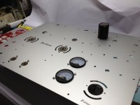
Top plate looks very good.
alecu7
Did you assemble the amp yet?
Top plate looks very good.
alecu7
Hi,
i have almost all parts together for my KT88 SE, looking forward to assemble all parts.
Greetings from germany,
Tobbe
Hi,
yes you can find it here:
Project | Homebuilt Hi-Fi - A user submitted image showcase of high quality home built hi-fi components.
yes you can find it here:
Project | Homebuilt Hi-Fi - A user submitted image showcase of high quality home built hi-fi components.
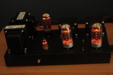
I built one. Changed the preamp valve to a 6DJ8, dropping the cathode resistor to 500R accordingly, and have the cathode resistor for the power tubes switchable between 480R and 560R to bias either 6550s/KT88s or EL34/6CA7/KT77/KT66. It sounds very good with both 6550s and KT88s in both Triode and 40% Ultralinear. Pentode sounds a bit harsh at the same gain level, but much louder
I used an Allied 6K7VG PT, Transcendar 10W 5k:8 OPTs, and a Hammond 193J P/S choke in C-L-C. Might have overbuilt the P/S a little bit.
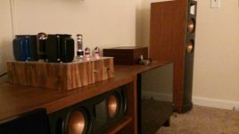
Pushing it through a pair of scratch-built Cornscalas, c. 100 dB/W, and it's got plenty of volume, even triode-strapped.
Built in three days, including hand drilling/dremeling the chassis. Only four blown fuses and one burn (from a hot tube) as collateral damage.
Does it sound better than my SS "reference" amp (Twisted Pear Sympatico dual-mono setup which, in passing, is fabulous)? Maybe. I'm not doing double-blind testing. I'm sure the THD for the tube amp is higher, but I also know that the majority component of the THD is 2nd harmonic distortion, which my ears actually like in moderate quantities. Do I like the fact that a homebuilt quartet of glowing vacuum tubes are driving my speakers, and might that bias my opinion of their sound? Yes. Am I enjoying listening as much as I enjoyed building? Absolutely.
My initial thought after an hour of listening was "what am I going to do with this Sympatico setup now?"
I used an Allied 6K7VG PT, Transcendar 10W 5k:8 OPTs, and a Hammond 193J P/S choke in C-L-C. Might have overbuilt the P/S a little bit.
Pushing it through a pair of scratch-built Cornscalas, c. 100 dB/W, and it's got plenty of volume, even triode-strapped.
Built in three days, including hand drilling/dremeling the chassis. Only four blown fuses and one burn (from a hot tube) as collateral damage.
Does it sound better than my SS "reference" amp (Twisted Pear Sympatico dual-mono setup which, in passing, is fabulous)? Maybe. I'm not doing double-blind testing. I'm sure the THD for the tube amp is higher, but I also know that the majority component of the THD is 2nd harmonic distortion, which my ears actually like in moderate quantities. Do I like the fact that a homebuilt quartet of glowing vacuum tubes are driving my speakers, and might that bias my opinion of their sound? Yes. Am I enjoying listening as much as I enjoyed building? Absolutely.
My initial thought after an hour of listening was "what am I going to do with this Sympatico setup now?"
Attachments
Hello
They reached the new high current regulators. These are the top model at 10m45s, hold up to 1000v. They work well. The Chinese were defective.
I tried one and do not know if I have to adjust as the anode consumption, or as the voltage to be applied to 6n2p.
Without the regulator and old 47K resistance measurements are:
- Anodo1. ---- 200V 4.45 mA
- Anodo2. ---- 200V 4.25 mA
Varies very little.
Installing always the same regulator (alternating the position) and adjusting a potentiometer measures are:
-Anodo1. Adjusting to a consumption of 4mA ----- 174v
-Anodo2. Adjusting to a consumption of 4mA ----- 168V
-Anodo1. Adjusting to a voltage of 200V----- 5.2mA
-Anodo2. Adjusting to a voltage of 200V----- 4.9mA
I do not know if I have to adjust to a consumer or a constant voltage, ie leave the two anodes adjusted to 200V, or adjusted to 5mA.
Regards
Would be able to give us brief review of the change in sound reproduction after you have installed the CCS? Is the sound change dramatic or not significant, in the end is it a worthwhile change? Thanks.
I agree with others that pentode mode sounds a little "harsh." MUCH more power, though. I wonder if there's a way to remedy that, other than using a UL tap from the OPT on the screen grid.
Hey all,
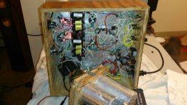
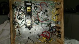
I'm resurrecting this thread in hopes that some folks are still watching it. I recently built one of these amplifiers (and this was my first successful tube amp and I consulted this thread a great deal as I built my project. I finished it and it functions well enough, but does have some issues. I'm hoping one of you fine people will be able to provide some advice.
Firstly, there is audible hum, but it only really becomes a problem at higher volumes. I suspect it's my wiring which is all over the place, but I was still careful with heater wire placement and twisting. I originally used twisted 22g wire in lieu of actual shielded wiring, but I swapped that out for some unused RCA cables which did nothing for the hum. My 6.3v was not center-tapped, so I created an artificial ground through two 100 ohm resistors tied to ground per some suggestions elsewhere. Any thoughts on this matter?
Secondly, when I turn the 2p3t rotary to pentode I get nothing at all, not so much as a whisper. I'm wondering if I connected it wrong, but every time I look at the schematic and the actual circuit, it seems correct. What could be going wrong there if I didn't wire it incorrectly? One possibility, in my mind at least, is that I shorted something in the switch. When I was doing initial voltage tests I slipped up somewhere right around the tie point for B+, the OT, and the wiring to the switch. Could that explain the problem?
For your consideration I have included several low res photos that may help illustrate what's going on. I know the inside of my chassis is a mess. I intentionally left my wire runs long in case I encountered any problems. I plan on cleaning all that up eventually. 😱
Attachments
For your second problem, you have sound un triode and Ultra-linear but nothind in pentode mode right?
Recheck the 2 pole 3 throw switch.
Can you post a clear photo of the switch and the Inside of the amplifier.
Recheck the 2 pole 3 throw switch.
Can you post a clear photo of the switch and the Inside of the amplifier.
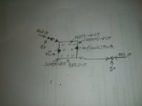
Yes, you are correct. UL and Triode mode function perfectly, only pentode does not work. I'll post a photo of the switch when I get home, but for now I'll post a crude drawing illustrating exactly how it's wired. I also forgot to mention that when I slipped doing my voltage tests there was a massive spark that blew the fuse.
Attachments
I think proper grounding is the most important thing to avoid hum.
See my layout and some hints to gounding: http://www.diyaudio.com/forums/tubes-valves/257760-diy-kt88-seul-2.html
See my layout and some hints to gounding: http://www.diyaudio.com/forums/tubes-valves/257760-diy-kt88-seul-2.html
I also think grounding may be the reason for hum. Do you have a star grounding scheme? have you connected the grounds from the input RCA to star ground? I remember when I did this my hum disappeared.
The best thing you can do is to get out the switch from the circuit and check every position with a multimeter. It look like you make a mistake... maybe you short the OT when you put the witch in pentode mode...
Also, only operate this switch when the power of your amplifier is off.
Also, only operate this switch when the power of your amplifier is off.
Well, I feel a bit stupid. I figured out why I wasn't getting anything in pentode mode. I had nothing tying the plate (pin 3) to the common wire of the OT accept for the triode position on the rotary switch. Duh! I'm going to rewire it after work and hopefully that should fix it. I doubt that will do anything for my hum problem, however. I was very contentious about star grounding everything to a single point on the chassis, so I'm not sure where a loop could be occurring. I did notice that the hum drops quite a but when I move the amp away from my AVR setup. It seems to hate HDMI cables. Not sure how to limit that interference because there isn't really any other decent place to place it.
Looking at your wiring, I would check how the heater wires are routed. If you have those either:
1) Not twisted tight enough (or not at all)
2) Running parallel to signal paths
3) Just flopping around inside of the case
You will end up with hum that yes, will get louder as you turn up the volume.
When you are running pentode, you do have a voltage source going to G2, correct? You aren't just disconnecting it are you?
- Status
- Not open for further replies.
- Home
- Amplifiers
- Tubes / Valves
- stereo SE kt88 build ... abdellah diyaudioprojects design