Your understanding is correct. The resistors are to prevent overcurrent.
But if we add series resistors in series with the rectifiers, we are increasing the source resistance of the power supply, and this creates problems in the bass range, because the output tube drives both the output transformer and the power supply resistance. So we lose a little output power too. People use regulator supplies, in order to have as little resistance as possible, so why would anyone want to make it worse?
Guys I am running this amp with SS rectifier.
and no stand by switch is that okay or could it
be a problem down the road.
Scott
and no stand by switch is that okay or could it
be a problem down the road.
Scott
Guys I am running this amp with SS rectifier.
and no stand by switch is that okay or could it
be a problem down the road.
Scott
If you don't like standby switches It would be better to fit a thermistor in the transformer primary, in order not to stress the first power supply capacitor at turn-on. This will allow you to use a smaller rated mains fuse. That's the minimum you can do without delay circuits etc.
Kt88 is running pretty conservatively in this circuit, it will be fine IMHO.
Guys I am running this amp with SS rectifier.
and no stand by switch is that okay or could it
be a problem down the road.
Scott
i would put in a delay circuit ,you find the on ebay for a nice price
it will expand your tube live
regards ko
Could you point me to one of these on Ebay.
Thanks,
Thanks,
i would put in a delay circuit ,you find the on ebay for a nice price
it will expand your tube live
regards ko
Could any one teach me that will it possible to change the bias of an EL34 into KT88. Because i would like to try the KT88 with the orchestral music. And the original bias of the EL34 is a // circuit with 390 15W and 100uF, 63V, which turns out about 26.9V &67mA bias. Will KT88 draw much current than the EL34? cause the transformer might not enough.
Please help Regards
Please help Regards
Could any one teach me that will it possible to change the bias of an EL34 into KT88. Because i would like to try the KT88 with the orchestral music. And the original bias of the EL34 is a // circuit with 390 15W and 100uF, 63V, which turns out about 26.9V &67mA bias. Will KT88 draw much current than the EL34? cause the transformer might not enough.
Please help Regards
What transformer are you using?
Are you saying your cathode resistor is 390R for the EL34? If so, I beleive that is a bit low for the EL34 all things else being equal to the original design.
If I recall correctly (you can refer to the schemtic at the beginning of this thread) the original design called for a 560R cathode resistor for the EL34 and then used a 3K to parallel the 560 to bring the cathode value down a bit for the KT88 operation (470 i beleive is the parallel equivalent)...
Again, this was the preference of the OP, not set in stone.....
With 390 on the cathode you shouldnt have too much issue as long as your OPT is rated for it...
Last edited:
Hi vinodt1347; re:the resistance of the OPT~ 20W 2K5-3K5SE < with extra NFB 16ohms
the old design of my amp can interchange into pentube and tritube mode .
the old design of my amp can interchange into pentube and tritube mode .
Not sure of your B+ etc.
Please check the link below - gives a lot of info. on design. Your OPT might just work though it may be preferable to use a higher primary reflected load of around 5K.
The Valve Wizard -Single Ended
Please check the link below - gives a lot of info. on design. Your OPT might just work though it may be preferable to use a higher primary reflected load of around 5K.
The Valve Wizard -Single Ended
Yeah, the design originally calls for a 5k primary...
Is this amp already up and running? Are you using the 3.5K primary?
If you are already using the 3.5K primary with a 390-400R cathode resistor I bet the KT88 will work better than the EL34 as you have it already set up.
Is this amp already up and running? Are you using the 3.5K primary?
If you are already using the 3.5K primary with a 390-400R cathode resistor I bet the KT88 will work better than the EL34 as you have it already set up.
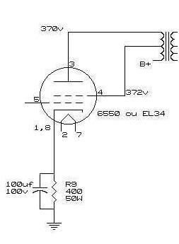
RE: vinodt the B+ is marked in the graph
Re: jmillerdoc the amp is running and i am using a pentube mode which connected to the B+ , 2K5 with the grid and 3k5 with the anode. but will you told me the current of the KT88 i think it might over load
Re: jmillerdoc the amp is running and i am using a pentube mode which connected to the B+ , 2K5 with the grid and 3k5 with the anode. but will you told me the current of the KT88 i think it might over load
Last edited:
Z = (Vin / Vout) squared.
if Z = Va^2 / Pa : Z = 380^2 / 25 Z =~ 5800
what is the use of this Z for plotting the load line and define the operation point?
if Z = Va^2 / Pa : Z = 380^2 / 25 Z =~ 5800
what is the use of this Z for plotting the load line and define the operation point?
Would you teach me how to define the current flow of the EL34B and the KT88, which the main transformer might over load. I have check the design of this post, which turns out the main transformer is rated as 600V C.T. @ 230mA. And my old transformer is a 600V C.T. @ 150mA. I think this is not enough at all. But with in a Class A design it might draw much less power than Class AB.
So would it possible to change the bias of the old setting and replace the EL34?
Regards~
So would it possible to change the bias of the old setting and replace the EL34?
Regards~
I have plot the graph and i am not sure is this right or not>
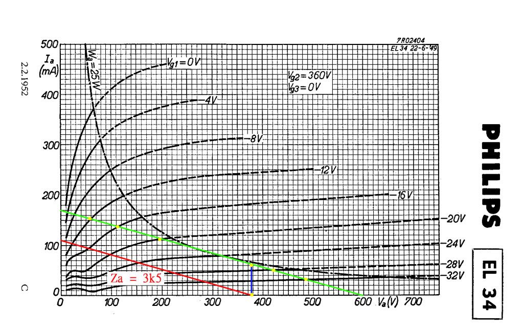
Looks okay, just remember the anode voltage in the plot is from Anode to Cathode, not from B+ to ground.
Re: costis_n :in this point > ( remember the anode voltage in the plot is from Anode to Cathode, not from B+ to ground. )
i don't understand why? the link from vinodt1347 said that the voltage across the transformer is only couple voltages, and i am know why. But the graph is telling us??
i don't understand why? the link from vinodt1347 said that the voltage across the transformer is only couple voltages, and i am know why. But the graph is telling us??
First of all. this amplifier is triode or ultralinear, so you have to use the correct graph. They re all in the datasheet.Well in my transformer it is more like 20 Volts. Don't listen to what other people with other transformers say, you have to measure it yourself. So you have to measure the voltage at the anode.
Then you have to adjust the cathode resistor so that the cathode is around where you want it.
Then you plot your load-line to see if it is okay.
Then you have to adjust the cathode resistor so that the cathode is around where you want it.
Then you plot your load-line to see if it is okay.
- Status
- Not open for further replies.
- Home
- Amplifiers
- Tubes / Valves
- stereo SE kt88 build ... abdellah diyaudioprojects design