"So, it's a sort of "anti-bump" at power off?"
Yes, quick switch off
Tomorrow I can send you my sim file ...
Yes, quick switch off
Tomorrow I can send you my sim file ...
I would say that if you have one rectifier on each transformer winding it may matter wich one you connect to.
Then you must connect AC to one of the windings on positive side rectifier.
BR
Figge
Then you must connect AC to one of the windings on positive side rectifier.
BR
Figge
Thanks, but my problem is that I'm unable to see it @ the simulator (LTSpice).
It works, I have non doubts, but I like to check it's properties before I order the PCB and the components.
It works, I have non doubts, but I like to check it's properties before I order the PCB and the components.
Hi Sir,
Well got your order with many thanks~
Sorry to bother you, but there is an issue that we want to confirm with you before proceeding.
1) As shown below, all drill hole sizes in your files are perfect integers.
We wonder that if your files is production files can be used for production directly without any compensation/optimization, in other word, is other supplier produced this PCB for you with this files before?? Yes or NO??
2) As shown below, should we cut out 2 indicated slots in KO layer from PCB? Yes or NO??
I have received this mail from the GLCPCB.
Please LKA can you help?
Attachments

Last edited:
thimios, jlcpcb produced this PCB before without any problem look at
Post #154,
I sent you spare right? how did they works?
Post #154,
I sent you spare right? how did they works?
I didn't finalize this yet.thimios, jlcpcb produced this PCB before without any problem look at
Post #154,
I sent you spare right? how did they works?
I have some missing parts.
Thank you for your answer!
As Sprint Layout does not support non circular plated holes directly, I used a trick YouTube. (TILE function, many circular pads in close proximity)
Maybe GLCPCB did not understand it, try JLCPCB.
Thanks Dear,my mistake...the mail is from JLCPCB.
JLCPCB Support
Last edited:
I tried to upload the gerber to JLCPCB and I had no problems.
Is there anything hidden?
Is it worthwhile to have 2 oz for the copper weight? (The price increases a lot).
Thanks
An externally hosted image should be here but it was not working when we last tested it.
Is there anything hidden?
Is it worthwhile to have 2 oz for the copper weight? (The price increases a lot).
Thanks
I haven't any problem uploading gerber to JLCPCB.I tried to upload the gerber to JLCPCB and I had no problems.
An externally hosted image should be here but it was not working when we last tested it.
Is there anything hidden?
Is it worthwhile to have 2 oz for the copper weight? (The price increases a lot).
Thanks
After payment send i received the above mail.😕
Any more spare PCB?thimios, jlcpcb produced this PCB before without any problem look at
Post #154,
I sent you spare right? how did they works?
I'm in Italy ...
Thanks
Yes PM with Postmail address..Any more spare PCB?
I'm in Italy ...
Thanks
I'm interested in obtaining quotes for these gerbers as well.
Are the answers to Thimios' post 205 - Yes and Yes?
Perhaps to stop the confusion there should be a round hole version. Just suggesting.
Are the answers to Thimios' post 205 - Yes and Yes?
Perhaps to stop the confusion there should be a round hole version. Just suggesting.
Mouser Electronics, Inc. France
thimios, You have to check... should be good. Looks like the Bzx85c5v6 is obsolete
thimios, You have to check... should be good. Looks like the Bzx85c5v6 is obsolete
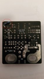
For some reason I could not fit the surface mount resistor on the back of the PCB so I soldered in a through hole resistor instead. See photo.
I will double up on my Mosfets to reduce the RSD for a certain amp that I am building that doesn't have a high damping factor. Boards are not tested yet.
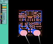
I think the design is great and very big thanks to LKA but my preference would be for the boards to be a little larger as they are tiny.
I will double up on my Mosfets to reduce the RSD for a certain amp that I am building that doesn't have a high damping factor. Boards are not tested yet.
I think the design is great and very big thanks to LKA but my preference would be for the boards to be a little larger as they are tiny.
Attachments
The pcb is intentionally so small. Usually there is little space around the output terminals. (at least in my amplifiers).
The board has two smd resistors, I forgot them to add as TH components in the design process and I was lazy to redesign the pcb.
Who has completed the pcb ? Does it work?
The board has two smd resistors, I forgot them to add as TH components in the design process and I was lazy to redesign the pcb.
Who has completed the pcb ? Does it work?
- Home
- Amplifiers
- Solid State
- SSR for speaker protection?