You're welcome 🙂Thanks a lot! This is really nice. The PVA1354 seems to have become obsolete, but a very similar device is now active: PVA13N: https://www.infineon.com/dgdl/pva13n.pdf?fileId=5546d462533600a401535683928a291e selling for UKP 5.60 or so on Mouser: PVA1354NPBF Infineon / IR | Mouser United Kingdom
This is really nice. Rdson is 5 Ohm, not in the milliOhm range, but for signal switching, this is what we would call really low impedance, right? And it reduces the 3-device SSR of the relay switching board into a single 4-pin device. Really neat.
Maybe, an AQV212 would be more up to date. But I had never used one of these.
The tricks and tips for measuring are all in this thread. If you have a Focusrite, you should be able to do it. Trick is to use the balanced input on the Focusrite and use ASIO driver... [/URL]
... I am working on a small very compact 2-ch SSR DC protect version for head phone amps that might be perfect for analog line-level switching...
Thanks for the distortion measurement primer. Will try to see if I can replicate it.
And will wait for your small(er) signal switching circuit. 🙂
you should need only 1 optocoupler per pair if you put the mosfets source to source so both have 8v VGS when on.
Just to be sure:
Vds,max must be high enough for the full rail-to-rail voltage, right?
I think Vds > (rail-to-rail voltage)/2 ; clamping diodes or TVS used for protecting
http://hifisonix.com/wordpress/wp-content/uploads/2013/01/Simple_solid_state_relay_Updated.pdf
"You must not use mosfets with a lower Vds breakdown than your absolute maximum rail to rail
supply voltage – they will fail"
http://hifisonix.com/wordpress/wp-content/uploads/2012/08/Speaker-Relay-V1.03.pdf
"As a general point, note that not under any circumstances can the Vds rating of the mosfets
used be exceeded. The devices must be rated to carry the full +- rail voltage, plus some safety
margin."
Bonsai, can you clarify,please ?
Last edited:
If the amp is ever going to be used in bridged mode and if the rails are +/-50V the MOSFETs must be rated well above 100V, 120V at least.
Don't go overboard though, very high voltage ratings come with high on-resistance.
If amp is never going to be bridged, 60V MOSFETs will prevent either rail getting to the speaker hot terminal. I'd feel safer erring on the side of caution and assume rail-to-rail voltage as the minimum requirement.
Don't go overboard though, very high voltage ratings come with high on-resistance.
If amp is never going to be bridged, 60V MOSFETs will prevent either rail getting to the speaker hot terminal. I'd feel safer erring on the side of caution and assume rail-to-rail voltage as the minimum requirement.
The trick with sensing bridged output is you need two detector circuits sensing voltage referenced to ground. If the speaker relay is designed as a stereo unit it can normally be used to protect a single channel bridged amplifier. Connect one output to each of the amplifier output leads and the ground connection to the supply ground.
General rule of thumb is double the rail voltage for a minimum safe working voltage for the mosfets, even in non-bridged applications. When things go bad in the amplifier it's not always only the amplifier producing the voltages, there is a speaker that is usually recovering from the early onset of a failing amp that can also be producing some voltage.
General rule of thumb is double the rail voltage for a minimum safe working voltage for the mosfets, even in non-bridged applications. When things go bad in the amplifier it's not always only the amplifier producing the voltages, there is a speaker that is usually recovering from the early onset of a failing amp that can also be producing some voltage.
A friend of mine tried this modified circuit (just he leave the overcurrent circuit unpopulated.
The turn on delay function well but the dc detection isn't working,whatever is the value of dc present.
The green led D3(in series)with another led instead of optocoupler remain always on.
Circuit isn't functional even in simulation.
I will post his own pcb later.
Please help.🙂
The turn on delay function well but the dc detection isn't working,whatever is the value of dc present.
The green led D3(in series)with another led instead of optocoupler remain always on.
Circuit isn't functional even in simulation.
I will post his own pcb later.
Please help.🙂
Attachments
Last edited:
A friend of mine tried this modified circuit (just he leave the overcurrent circuit unpopulated.
The turn on delay function well but the dc detection isn't working,whatever is the value of dc present.
The green led D3(in series)with another led instead of optocoupler remain always on.
Circuit isn't functional even in simulation.
I will post his own pcb later.
Please help.🙂
My SSR works great. Both channels are powered by single +24V auxiliary psu. Check this video. DC thresholds ca -0.5V and +0.6V
YouTube
I guess, you have "ground problem". X1- and X3GND have to be connected in some way.
My SSR works great. Both channels are powered by single +24V auxiliary psu. Check this video. DC thresholds ca -0.5V and +0.6V
YouTube
I guess, you have "ground problem". X1- and X3GND have to be connected in some way.
Thanks LKA,we solved the problem.
Collector of T1 and emmiter of T3 isn't connected.

Gherber format
Hello LKA,
With what software you generate gerbers file? I try to import them (Sprin layout) to make minor adjust but there are problems with drill file.
Thank you, regards!
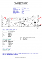
the finalized SSR2 protection
View attachment 765166
View attachment 765167
View attachment 765168
schematic and gerbers
SSR - Google Drive
Hello LKA,
With what software you generate gerbers file? I try to import them (Sprin layout) to make minor adjust but there are problems with drill file.
Thank you, regards!
Hi, those files were modified by manufacturer (pcbway). In Sprint-Layout you can't make oval holes, so I used "tile" function. Original gerbers are here:
ProtectSSR-v2.0-final.zip - Google Drive
ProtectSSR-v2.0-final.zip - Google Drive
Happy New year.
Have some intresting information regarding distortion.
Grabbed what I had in the drawers I used a UPC1237, VOM1271 and TO247 mosfets with RDS on at 0.09 ohm.
Worked ok for 8 ohms raising distortion ~0.002%, but in 4 ohms distortion went up to 0.44% !
Swapped the mosfets to ST TO220 devices. RDS on at 0.004 ohms resulted in significant lower distortion.
With 8 ohms load the difference are hardley measureble, and in 4 ohms it went up ~0.004%.
Have some Toshiba TK72 something on order to, I hope they will work.
BR
//Figge
It can be tricky to implement SS relays properly. Very low RDSon devices are required but layout and proximity to external noise can cause issues as well. I've seen significant increases in distortion when a control transformer is near by.
It can be tricky to implement SS relays properly. Very low RDSon devices are required but layout and proximity to external noise can cause issues as well. I've seen significant increases in distortion when a control transformer is near by.
Happy new year,
Oh, than I could have problems? What is causing the extra distortion... when the xfmr is near the fet's.
https://www.diyaudio.com/forums/solid-state/318946-ssr-speaker-protection-15.html#post5841649
I haven't actually had the time to investigate the issue too deeply yet (it's on my to do list though). I found this while taking some distortion measurements on the output of an amplifier I built and cured it by relocating the supply section of the protection system. I assume it's due to the gates picking up some AC voltage from the transformer though.
I'm lost... I'm unable to understand what an AC protection can be, so that I don't know where to connect the AC pin to my test amplifier (heavily unbalance in LTSpice).
I understand DC, OC, but not AC. Sorry about that.
It could be the reason why the circuit doesn't work in my simulations. I assumed that the circuit is powered by the amplifier dual mono PSU.
Sorry for the very dumb question.
I understand DC, OC, but not AC. Sorry about that.
It could be the reason why the circuit doesn't work in my simulations. I assumed that the circuit is powered by the amplifier dual mono PSU.
Sorry for the very dumb question.
AC detector, not protection. It tracks AC voltage on the transformer secondary winding (it doesn't matter which one, AC1 or AC2, not CT). When AC is lost, SSR is switched off in very short time and the delay circuit capacitor is also discharged.
Last edited:
So, it's a sort of "anti-bump" at power off?
So, I'm still left with my simulation that doesn't work.
But, it's a simulation. Models are far to be reliable and I must rely on what I read in the documentation.
Thanks
So, I'm still left with my simulation that doesn't work.
But, it's a simulation. Models are far to be reliable and I must rely on what I read in the documentation.
Thanks
- Home
- Amplifiers
- Solid State
- SSR for speaker protection?