
For the MOSFETs, Rod Elliott's design using Si8752 recommends TK72E12N1. 120V, 72A and 3.6mΩ Rds in a TO-220 package. Currently $2.53 at Digikey and Mouser (though out of stock at till May).
Hello,
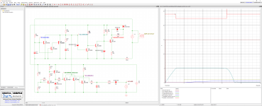
I tried to simulate your circuit and i dont get the same reaction time, especially for DC voltage protection.
I set a 1V DC offset on amplifier output @t=2s (speaker already connected) and R1/C1 100k/44uF filter gives 4.4s reaction time. simulation give this expected result.
so how did you get 1.1s ? am i missing something ?
I attached a picture of the simulation, i hope resolution is good enough.
Attachments
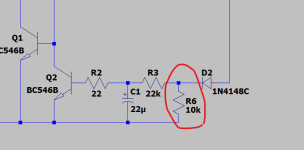
can you please tech me something about it.,what is the functionality and importance of these caps values,Two 22u in series is not 44u
Hi LKA,what is the current limiter that is used in this short circuit protection?short circuit protection in action (output 1kHz 34.5Vrms)
K300 SSR3 SHORT - YouTube
Hi, the amplifier board has two diodes (natural current limiter, see the Cordel book) and a voltage sensing circuit through output emitter resistors (two resistor and PC817 input). The output of the optocoupler then activates the OC input of the SSR.
"Hi, the amplifier board has two diodes (natural current limiter, see the Cordel book) and a voltage sensing circuit through output emitter resistors (two resistor and PC817 input). The output of the optocoupler then activates the OC input of the SSR."
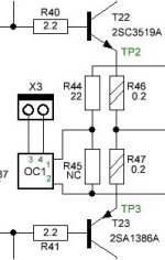
R44,45 is the voltage sensing circuit.
What is the two diodes natural current limiter?
R44,45 is the voltage sensing circuit.
What is the two diodes natural current limiter?
Agree.The SSR such as you mention use triacs and are unsuitable for use as a speaker relay because they would generate massive non linear distortion around the zero crossing point.
SSR's made using two power FET's and a floating photovoltaic coupler are the way to go and many have used these successfully. I would never go back to mechanical relays now.
This long thread has all the details:
Output Relays
Hi LKA,
I had the issue that the SSR was not directly switching of when mains were disconnected. The AC was taken before an active rectifier.
When disconnecting the cable to the AC connection, shut down was working correctly. When leavinig it connected (as ment) shut down took couple of seconds. Maybe the active rectifier using mosfet's with internal protection diode are causing this?
EIther way, I solved it with adding an additional load for the AC connection : A 10k resistor connected to GND after the 1N4148.
Attachments
- Home
- Amplifiers
- Solid State
- SSR for speaker protection?