Hello,
still one open issue, what is the minimum Uceo for the PC701. there are two different value of Uceo available , 35V and 70(80)V.
Thanks in advance
still one open issue, what is the minimum Uceo for the PC701. there are two different value of Uceo available , 35V and 70(80)V.
Thanks in advance
Hello,
still one open issue, what is the minimum Uceo for the PC701. there are two different value of Uceo available , 35V and 70(80)V.
Thanks in advance
Why PC701 ?
PC817 manufactured after 2002 has VCE0=80V. Or, you can try FODM3011/MOC3011.
sorry, typing error.
Thanks for suggestion. A lot of 817 optocouplers are offered with 35V Vceo (Lite-on, Everlight).
Thanks for suggestion. A lot of 817 optocouplers are offered with 35V Vceo (Lite-on, Everlight).
There's a couple issues you will have with a design like this. First, it's way too slow. The cone of the speaker would already be against the stop by the time that thing saw DC. Your detection needs to be happening in the microseconds realm, not milliseconds. Second, you have digital and analog circuits connected together, it's going to be noisy. If you are going to monitor two channels you'll have ground loop issues as well.
I reckon about 500 milli-seconds is ok for DC detect. 1/2Hz is still AC.
Any more and you are asking for trouble.
If the phase stays the same for 500ms then cut the relay.
My SSR speaker protector also checks for mains failure and cuts off speaker to stop power down pops. It has power up delay for same reason.
It also has short circuit protect, it has a very small resistor in series with speaker and detects voltage across it. You can set trip level on a trimmer.
I use a dual secondary mains transformer for power, one secondary for logic and the other for the power to mosfet gates.
One can use protection like this. On the left - DC detector, on the right - AC detector. Photovoltaic coupler is powered by CCS. R2,C3 - ON delay. T6 requires a heatsink.
View attachment 715137
Can anyone help me with understanding what T1, T2, T3, D1 and D2 are doing?
So if I understand correctly, T2s collector is held around the positive rail voltage (less one ~0.7V diode drop). If the amp output were to sit at rail voltage for enough time, C1 and C2 charge via R1. This will switch on T1 with base current supplied through D1. T1 collector is now pulled low which discharges C3, turning off the optocoupler.
Am I understanding this correctly?
Cheers.
If no DC at amp output, T1-T3 are all OFF. C3 is charged via R2, if voltage reaches zenerV+0.6V, T4 turns ON and T5 OFF. CCS (R4,R5,D5,T6) is released, now optocoupler can work.
When DC present at output, for example positive, T1 turns ON, this pulls down T4 base, T5 turns ON and CCS will be switched OFF.
D1 and D2 increase DC level thresholds.
My PCB design, holes 3-5mm, terminal distance 22.5-28mm, board dimension 46x50mm. Almost all components are TH.


I reckon about 500 milli-seconds is ok for DC detect. 1/2Hz is still AC.
I don't think its as simple as that - if the output suddenly shorts to a supply-rail,
you want to operate the relay as soon as possible. If the DC offset gradually drifts up to a volt or two you can cut the relay off at a leisurely rate. Using a low-pass filter before a threshold detector matches this well - fast operation on high voltage errors, slower for offset errors, and you can set the operating threshold to just allow 10--20Hz full swing signals through - that means the full voltage error will trigger detection in 50ms sort of timescale, much better for saving those voicecoils than 0.5s
If 0.5Hz signals are coming through the amp they are likely to damage the speakers anyway, basically thats DC that occasionally changes polarity!


Hello LKA,
Very nice and compact PCB and nice build.
Congrats! and thanks for sharing the gerbers.
regards
Prasi
Very nice and compact PCB and nice build.
Congrats! and thanks for sharing the gerbers.
regards
Prasi
Great progress
However I think there is a general mis-sunderstanding here on how DC detection works as well as speaker protection as well as the relationship between A/C and D/C. The DC sensors in use here all take about 250ms to detect DC. The response circuit takes a fraction of the time to activate whether its analog or digital
However I think there is a general mis-sunderstanding here on how DC detection works as well as speaker protection as well as the relationship between A/C and D/C. The DC sensors in use here all take about 250ms to detect DC. The response circuit takes a fraction of the time to activate whether its analog or digital
Am still within my time frame 'couple of weeks' lets keep the faith😉
Thanks for the great ideas hopefully in the coming weeks will post something we can all play with
Great progress
However I think there is a general mis-sunderstanding here on how DC detection works as well as speaker protection as well as the relationship between A/C and D/C. The DC sensors in use here all take about 250ms to detect DC. The response circuit takes a fraction of the time to activate whether its analog or digital
Have you properly simulated or tested the circuit? 250mS doesn't sound right.
Response time
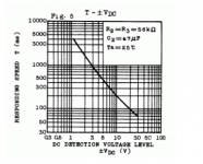
Many DC detections are working on the same principle.
The TA7317 chip is the one I'm using combined with a SSR relay.
The response time of the TA7317 is depending on the RC input filter AND the value of the DC input voltage.
See graph below.
Many DC detections are working on the same principle.
The TA7317 chip is the one I'm using combined with a SSR relay.
The response time of the TA7317 is depending on the RC input filter AND the value of the DC input voltage.
See graph below.
Attachments
Basically there are four items were protecting
1. Output transistors
2. PCB
3. Speaker
4. Transformer
If someone uses too lower power speakers they wont be protected.
Or if they drive the speakers at their max load or just over then the speaker will still fail first.
I designed my own speaker protector using SSR but added programmable over current detect and mains fail power up/down detect.
It ended up quite a big pcb but there is a lot of protection there.
Nice chart thanks for clearing the matter😉
Many DC detections are working on the same principle.
The TA7317 chip is the one I'm using combined with a SSR relay.
The response time of the TA7317 is depending on the RC input filter AND the value of the DC input voltage.
See graph below.
Your correct Nigel, if the speaker has low wattage most protection schemes may fail
If someone uses too lower power speakers they wont be protected.
Or if they drive the speakers at their max load or just over then the speaker will still fail first.
I designed my own speaker protector using SSR but added programmable over current detect and mains fail power up/down detect.
It ended up quite a big pcb but there is a lot of protection there.
- Home
- Amplifiers
- Solid State
- SSR for speaker protection?