Thanks,
The DC sensor is actually analog, the capacitor takes 250ms to charge to a voltage that can be interpreted by arduinos digital read (kindly post your DC sensor) , its like a match made in silicon heaven, the arduino is real time within 5us for digital and between 100us to 300us for analog, you can get faster speeds with a skip here and there
isolation of circuits using optocouplers, isolation transformers, relays etc does help, this was not investigated in the above test
"Your detection needs to be happening in the microseconds realm, not milliseconds:" One might argue that whether its AC or DC might not matter much as the current (VI limiters and fuses do a great job however for a micro controller we can tell it using a resolution of 5us if you see 30A on 2sc5200 protect, however amplifier supply caps are charged, so plan b becomes disconnecting speakers or the short. relay turn off has its delay and assume that our relay whether solid state or mechanical has higher current capability)
https://www.electronics-tutorials.ws...s-voltage.html
YouTube
Thanks again for sharing
There's a couple issues you will have with a design like this. First, it's way too slow. The cone of the speaker would already be against the stop by the time that thing saw DC. Your detection needs to be happening in the microseconds realm, not milliseconds. Second, you have digital and analog circuits connected together, it's going to be noisy. If you are going to monitor two channels you'll have ground loop issues as well.
I've found the best approach is to use a good old fashion analog DC detection circuit connected to the input of a high speed optoisolator. Use the output from the optoisolator to change the state of an interrupt pin on your microcontroller. I use a dual input optoisolator and have one output connected to the microcontroller and the second directly disconnecting the SS relay allowing for a redundant shutdown of the SS relay with the microcontroller latching it off, meanwhile the microcontroller shuts down the amp at the same time minimizing further damage to the failed output stage.
how much voltage are we dropping across the SSR?
Were switching these mosfets at audio frequency, is it audible?
Were switching these mosfets at audio frequency, is it audible?
Attachments
Last edited:
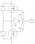
Here's a schematic of our speaker relay boards. Voltage drop across the SS relay isn't measurable with properly selected mosfets, they 2.5 milliohms resistance in switch mode on a good mosfet. Switching is inaudible, the only possible noise wound be turn on thump from DC offset which shouldn't be there, otherwise it shouldn't turn on.
https://www.infineon.com/dgdl/Infin...n.pdf?fileId=db3a30431ce5fb52011d1ab1d9d51349
https://www.infineon.com/dgdl/Infin...n.pdf?fileId=db3a30431ce5fb52011d1ab1d9d51349
Attachments
Last edited:
Thank you, thats a serious mosfet. Specs show one needs 5v to turn it fully on. In tests does the turn on thump prevent the relay from turning on? seeing that your not implementing delay else where. Class A buddies might be upset adding an active switching stage to the 'pure' signal path
Much of the analog logic can also be easily handled digitally . Will set up a demo to investigate pros and cons of both sometime later next week
Much of the analog logic can also be easily handled digitally . Will set up a demo to investigate pros and cons of both sometime later next week
Here's a schematic of our speaker relay boards. Voltage drop across the SS relay isn't measurable with properly selected mosfets, they 2.5 milliohms resistance in switch mode on a good mosfet. Switching is inaudible, the only possible noise wound be turn on thump from DC offset which shouldn't be there, otherwise it shouldn't turn on.
https://www.infineon.com/dgdl/Infin...n.pdf?fileId=db3a30431ce5fb52011d1ab1d9d51349
Last edited:
Turn on delay and latching off are controlled by the microprocessor in our system where it's easy to adjust time intervals. With the circuit in the .pdf any DC above 1.2V will prevent the relay from turning on.
Some people can hear the difference between blue and red wire. If someone chooses to believe the nonsense that a couple milliohm resistance (this is less than most relay contacts) will cause an audible difference in a system they likely won't be running any protection anyways.
Some people can hear the difference between blue and red wire. If someone chooses to believe the nonsense that a couple milliohm resistance (this is less than most relay contacts) will cause an audible difference in a system they likely won't be running any protection anyways.
Hi LKA i would like use your great SSR protect circuit and Prasi PCB design, What is the best match for you for obsolete BZX83C diodes, and could you also confirm that R4 is 1W and all other resistors are 0.6W
Thanks
Hi LKA i would like use your great SSR protect circuit and Prasi PCB design, What is the best match for you for obsolete BZX83C diodes, and could you also confirm that R4 is 1W and all other resistors are 0.6W
Thanks
Hi, You can use any 100-500mW zener. R4 has 100mW dissipation (at 50Vcc), so 0.4-0.6W resistor is fine.
Its good to drive the mosfet gates directly from the DC detection circuit (fast) and then to use the uController to hold it off or do any other housekeeping/detection etc.
I am switching a 60A 10ms pulse in <100uS using 2 x VOM1271 - each provides about 16uA forward current, so total drive is 32uA per channel.
Mosfets don't suffer from secondary breakdown and can handle very high peak energy levels - see the data sheet of your respective mosfet for details. You just have to select a mosfet with a suitable energy rating - there are formulas for estimating the peak energy based on current and rise time. With lower energy rated mosfets, you will need to switch faster to stay within the energy dissipation boundary.
On my gear, I look at gross current overload (sensed directly across the emitter degen resistors with an opto), DC offset (typically +- 1.5V~2V) using a 3 transistor DC detect circuit. Both of these switch the mosfet gates OFF directly and also feed into the uController.
The 2nd DC detect loop is off the DC servo. I trim the DC offset to zero with a pot so that under normal operation the DC servo output is only around +-100mV. If there is a gross DC offset fault, the servo output slew to one of the opamp supply rails and that's the other input that drives the mosfets directly. If there is a partial short, the servo output will also increase dramatically, so these faults are also caught in most cases.
In effect, the microcontroller is in parallel with the DC fault detection circuits (so reliability of catching a problem is improved) and will decide whether to keep things off or not depending on the fault - e.g. a temporary short circuit of the output. For example, If there is a gross short, I turn the amp off and it won't come on for at least 3-4 minutes to make sure all the output transistor die temperatures have cooled off.
I monitor heatsink temperature as well.
If you are using a uController, make sure your watchdog facility is used - you don't want it hanging up.
I've also measured my amps with the SSR in situ and bypassed - the distortion is below the QA401 noise floor so the SSR can be effectively discarded as a source of non-linearity. This does stand to reason since in the ON condition, the total SSR end to end resistance is 5~10 milliohms while the load is 3 orders of magnitude higher - any ON resistance modulation (and there is very little of that) is completely buried by factors.
Anyway, good to see a general interest in SSR for loudspeaker protection rather than relays - I have to thank Michael Bean for introducing me to the idea in 2012
🙂
ok i will use BZX55B5V6 AND BZ55B10, ThanksHi, You can use any 100-500mW zener. R4 has 100mW dissipation (at 50Vcc), so 0.4-0.6W resistor is fine.
Have you seen this thread?
How to build a 21st century protection board
Thanks Harry will have a look at it 😉
Turn on delay and latching off are controlled by the microprocessor in our system where it's easy to adjust time intervals. With the circuit in the .pdf any DC above 1.2V will prevent the relay from turning on.
Some people can hear the difference between blue and red wire. If someone chooses to believe the nonsense that a couple milliohm resistance (this is less than most relay contacts) will cause an audible difference in a system they likely won't be running any protection anyways.
Thanks, my test bed isn’t ready yet, will put all these ideas to good use
I am switching a 60A 10ms pulse in <100uS using 2 x VOM1271 - each provides about 16uA forward current, so total drive is 32uA per channel.
I've also measured my amps with the SSR in situ and bypassed - the distortion is below the QA401 noise floor so the SSR can be effectively discarded as a source of non-linearity. This does stand to reason since in the ON condition, the total SSR end to end resistance is 5~10 milliohms while the load is 3 orders of magnitude higher - any ON resistance modulation (and there is very little of that) is completely buried by factors.
🙂
Thanks for the great ideas hopefully in the coming weeks will post something we can all play with
My SSR speaker DC protect uses a PIC micro.
If it sees DC for > 500mS it turns off the relay.
It also has anti thump power on delay.
I used a opto coupler from the PIC to the mosfet gates.
I used a dual secondary mains transformer, one secondary for the PIC and the other for the mosfet gate power supply.
I buffered the output of the opto coupler with a totem pole.
To do without a heat sink I used very low RDSon mosfets.
I can get upto 500WRMS into 4 ohms with my current mosfets with no heat sink.
Where's the schematic Nigel? Is it fail safe?
Its not fail safe. If components fail it could stay on.
https://www.flickr.com/photos/49481917@N00/46447689134/in/dateposted-public/
Hello,
I'm comparing Mosfet datasheets to select proper ones for my SSR speaker protection.
The amplifier PSU is +-53Vdc and capable of driving 2R loads without much effort (not that I ever will do this 🙂
This fet is available and seems good in this application.
https://www.infineon.com/dgdl/irfps3810pbf.pdf?fileId=5546d462533600a40153562ce01f2035
Hello,
I'm comparing Mosfet datasheets to select proper ones for my SSR speaker protection.
The amplifier PSU is +-53Vdc and capable of driving 2R loads without much effort (not that I ever will do this 🙂
This fet is available and seems good in this application.
https://www.infineon.com/dgdl/irfps3810pbf.pdf?fileId=5546d462533600a40153562ce01f2035
Looks good but will dissipate 8 watts without a heat sink which is too much.
A 6 degree c/watt heat sink on each mosfet will bring it into range.
30 amps * 30amps * 0.009 = about 8 watts peak. or 4 watts RMS.
Hi LKA,
i plan to use the speaker protection for my amps with the latest PCB from Prasi.
Most of my amps are running at a supply voltage from 40 to 65 V DC. What need to be modified to work proper?
- change of R3, R6 and R8 to adopt to higher DC voltrage (value?)
- change of R4 to adopt to higher DC voltrage (value?)
- is Vds max 100V for T9/T10 sufficient, since the suggested type by Prasi has only a Vds max of 60V
- V CE max of the PC701 (35V sufficient ?)
Best regards
Günni
Hi LKA,
i plan to use the speaker protection for my amps with the latest PCB from Prasi.
Most of my amps are running at a supply voltage from 40 to 65 V DC. What need to be modified to work proper?
- change of R3, R6 and R8 to adopt to higher DC voltrage (value?)
- change of R4 to adopt to higher DC voltrage (value?)
- is Vds max 100V for T9/T10 sufficient, since the suggested type by Prasi has only a Vds max of 60V
- V CE max of the PC701 (35V sufficient ?)
Best regards
Günni
Hi, for 65V PS you should use 150V mosfet like IPI051N15N5. Change R4 to 22k-27k. T6 will dissipate 0.9W
Hi, for 65V PS you should use 150V mosfet like IPI051N15N5. Change R4 to 22k-27k. T6 will dissipate 0.9W
The above one has rather low avelanche energy specs compared to what Bonsai is referring to in his ssr speaker protection paper.
I'm looking to IRFP4568PbF as SSR on a 53vdc amp. All specs seem good, as this s a big FET, capacitances are rather high... 2 photovoltaic drivers in parallel?
Gr
- Home
- Amplifiers
- Solid State
- SSR for speaker protection?