That looks like a good solution. I'm glad you added the diodes D7 and D8 because many amps don't include them.
Can you give us some guidance on how to select the resistor values RS1 and RS2 for the over current circuit?
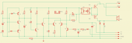
Choose RS1=100R (current limiter for IR led)
PC817 has forward voltage approx 1V. If RE=0.22R then Ith=1V/0.22R=4.5Ap
If you need higher current threshold, add RS2 (voltage divider).
RS2=100R Ith=9Ap, etc
Maybe an overkill, but I like over-designing things:
http://ixapps.ixys.com/DataSheet/DS100845B(IXFN300N20X3_).pdf
http://ixapps.ixys.com/DataSheet/DS100845B(IXFN300N20X3_).pdf
Choose RS1=100R (current limiter for IR led)
PC817 has forward voltage approx 1V. If RE=0.22R then Ith=1V/0.22R=4.5Ap
If you need higher current threshold, add RS2 (voltage divider).
RS2=100R Ith=9Ap, etc
Thanks
I think that i have to speak to Prasi! 😉
Hello thimios,
you never did speak to me about this!😡
Otherwise I would have made it earlier.😀
I stumbled here by chance while making APEX SSR protect
 .
.Thanks to LKA for the design.🙂
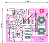
Still a rough design, need to see if binding post on a side can support PCB components. Otherwise , a hole for plastic standoff on the left side would provide necessary support for the PCB.
Regards
Prasi
Attachments
Any chance this could be made to work with a supply voltage of up to +/- 90 volts dc ?
Also, are u thinking of selling the pcbs ?
Thanks
Also, are u thinking of selling the pcbs ?
Thanks
What is apex ssr
go to apex 100W amp thread and read a few posts.
Last edited:
Any chance this could be made to work with a supply voltage of up to +/- 90 volts dc ?
Also, are u thinking of selling the pcbs ?
Thanks
is the question meant for me or LKA?
I think LKA posted a circuit for 90V. (Just from memory glancing through the thread.)
I have been searching for a proper SSR protect too for a 60-100W home amplifier, so stumbled here by chance. I made the PCB for diyers, so thats why single sided, (for home etching).
regards
Prasi
Hello thimios,
you never did speak to me about this!😡
Otherwise I would have made it earlier.😀
I stumbled here by chance while making APEX SSR protect
Thanks to LKA for the design.🙂
Still a rough design, need to see if binding post on a side can support PCB components. Otherwise , a hole for plastic standoff on the left side would provide necessary support for the PCB.
Regards
Prasi
Hi, You can leave out D1,D2 (or short them out).The detection threshold will be lower. If you want more symmetrical detection, just short out D2.
Hi my friend!Hello thimios,
you never did speak to me about this!😡
Otherwise I would have made it earlier.😀
I stumbled here by chance while making APEX SSR protect
Thanks to LKA for the design.🙂
Still a rough design, need to see if binding post on a side can support PCB components. Otherwise , a hole for plastic standoff on the left side would provide necessary support for the PCB.
Regards
Prasi
I see you very busy and i don't want to stress you. 🙂
You are a pcb machine!
All the best for you and LKA
BTW if i will have the final schematic and the black&white pcb i can test this soon.
Last edited:
Hi everyone,
Is there a simple safe way to add a 'mute switch' to this circuit? (with maybe an indicator led too?)
Is there a simple safe way to add a 'mute switch' to this circuit? (with maybe an indicator led too?)
Hi my friend!
I see you very busy and i don't want to stress you. 🙂
You are a pcb machine!
All the best for you and LKA
BTW if i will have the final schematic and the black&white pcb i can test this soon.
YOU can tell me anytime😀.
I will post black and white and the schematic, once I am done refining the design.
Pl note that this circuit is based on post no. 31 by LKA.
Regards
Prasi
Hi everyone,
Is there a simple safe way to add a 'mute switch' to this circuit? (with maybe an indicator led too?)
See post 58, overcurrent circuit can be used as MUTE also. Just connect latching switch to terminal X4.
Ah, simple indeed and easy to implement - a double pole switch for the indicator led too - thanks
Thank you LKA for your suggestions. I will keep them on the pcb for the present. One could short or just remove D2 as per his preference.Hi, You can leave out D1,D2 (or short them out).The detection threshold will be lower. If you want more symmetrical detection, just short out D2.
Regards
Prasi
Hi Prasi
We appreciate your work.
Is it possible to get rid of the link that goes from the Mosfet to the speaker, with a track?
We appreciate your work.
Is it possible to get rid of the link that goes from the Mosfet to the speaker, with a track?
Thank you LKA for your suggestions. I will keep them on the pcb for the present. One could short or just remove D2 as per his preference.
Regards
Prasi
Another suggestion. Connect T5 collector to D3-D7 junction. C4 discharging will be quicker when AC is lost. (component numbering, post 65)
Check my last schematic, post 58.
Interesting thread, have been playing around with using arduino analog pins to check for DC and resolve within 100ms one might say that that is too slow considering above presumably detects and resolves in 380us. The AC lp filter 100k + 10uf will feature a 3.3 volt zener across the capacitor to protect the arduino input, other pins will check temp, over current and short circuit featuring lean code and timer interrupts. output pins will shut off power and trigger speaker protection, plus printing out on LCD the protection event.
Yes the analog domain is faster, however the digital domain is still fast enough.
Yes the analog domain is faster, however the digital domain is still fast enough.
- Home
- Amplifiers
- Solid State
- SSR for speaker protection?