Yes, obviously. I will do this after I again have re-checked everything. Feels so weird...to still make a swapping mistake. Will come back on this. Thanks again.The obvious thing to do is to try swapping the wires going to the mid and tweeter to see if that resolves the problem.
Sure, I can imagine something like that. I think in this case I know the speakers very well (have them for 32 years now) and this sound surely is not because of new electrolytics vs the old ones. I suspect the error down to a basic wiring mistake for now (although not sure yet). Thanks.Once you’ve sorted and confirmed your connections, keep in mind that one of the things that usually happens to older electrolytic crossover capacitors is that they will gain capacitance. This changes the function and sound…
This may be an adjustment if you have been using the speakers in a well used state.
this sound surely is not because of new electrolytics vs the old ones.
Phase was not suggesting that, he was talking about after you had the wiring sorted out.
From your posts I can tell that you are new to electronics, have read/ heard a lot but no practice.
The most simple way to check what you have there and how it is connected correctly ist to draw a simple schematic of the x-over. It is a limited number of parts...
Maybe you even know some place on the (Dutch) internet where one is printed. Post it here and pictures of your x-over and we can find any fault I'm sure.
The x-over of your loudspeaker is the usual "entry level quality" product from German Intertechnik /Kerpen. They produced them for countless European speakers over the last 50 years. The better x-over's from IT used film foil capacitors in series with mid and tweeters. Usually a developer builds and tunes the speaker for a large company like Phillips, then the schematic is turned over to IT with a cost limit. Your x-over is such an outcome.
To replace the caps was a very good idea, I hardly ever found a vintage x-over without at least one cap far off. It is more expensive to measure them all then to replace them and be of the hook for the next decade. Some cap's start to distort and are sure a major cause for such speakers trown away.
If you draw or show a schematic, you also may get an idea what parts may be worth to get replaced by someting a little better.
In post 50, there is an image of the rear of the board. The commentary says that soldering went well with all the tin dots bright.
If that image represents the board after soldering, there is no evidence of any connection between the component wires and the board tracks.
Craig
If that image represents the board after soldering, there is no evidence of any connection between the component wires and the board tracks.
Craig
Yes I saw that and I assumed from what was said they had all been tested. If not then they should be. It doesn’t pay to allow solder to get recycled, it is better that you remove it and renew it. Still, at this stage I’d simply begin with testing each joint.
Indeed. If any or all the joints are questionable it could well explain the weird frequency balance the OP is reporting,
Reading Jenson's description in post #50, I believe he has carried out the soldering process correctly.
I'm sorry for this confusion. No, this picture is right after I put the new capacitors in place. Adding glue followed and then, a day later, I soldered the connections. And that went very well, describing this in #50.In post 50, there is an image of the rear of the board. The commentary says that soldering went well with all the tin dots bright.
If that image represents the board after soldering, there is no evidence of any connection between the component wires and the board tracks.
Craig
From a diagnostic point of view it would be prudent to check all joints for continuity, then test them for shorts, then expand the scope of testing with other passive and live tests.
Post No 1 shows how the speaker are connected. The colored threads go to the speaker positive. Speaker positive is found if you connect a 1.5 Volt battery and the cone or dome moves away from the speaker.
!!!!!!!!!!!!!!!!
Please do not get confused: At the x-over speaker positive may be connected to negative! This is to keep the phase constant, which changes from the coils and caps.
!!!!!!!!!!!!!!!!
Maybe you thougt this was wrong?
If you compare the length of the wires you will find the tweeter probably to be a little longer than the one to the mid.
!!!!!!!!!!!!!!!!
Please do not get confused: At the x-over speaker positive may be connected to negative! This is to keep the phase constant, which changes from the coils and caps.
!!!!!!!!!!!!!!!!
Maybe you thougt this was wrong?
If you compare the length of the wires you will find the tweeter probably to be a little longer than the one to the mid.
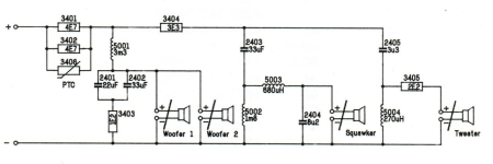

Thanks for the schematic, Turbo!
We can now see that the PTC in parallel with the two 4.7 ohm resistors forms the overload protection circuit for the entire speaker. Here's how it works:
When operating normally the effective resistance of the protection circuit will be smaller than that of the cold PTC (a small fraction of an ohm).
During a prolonged overload, the resistance of the PTC will rise and so will the effective resistance of the protection circuit (perhaps to around 2 ohm) thus reducing the current flowing to the loudspeaker system.
EDIT: Edited due to brain fog!
Last edited:
Yes, shorting out the PTC as Jenson has done has shorted out the entire protection circuit.
I got a bit carried away thinking he might have to reinstate it! 😗
I got a bit carried away thinking he might have to reinstate it! 😗
Galu and Turbowatch2, both many thanks for your time and input. Also thanks for the schematic; I found it myself too (see attached picture).
Like you said Turbowatch2, the cable to the tweeter was a BIT longer...I did that check also. Next to a small bend in that cable (which was made when I pulled it out) I could more or less trace back that I actually did switch the cables...which I cannot believe...just a total brain lock-down somewhere when I wrote it down.
So, I again changed cables yesterday, had to wait for a day for re-glue, and voila, the sound is back as it should be!! I feel really silly 🙂
Anyway, so happy that it came down to such a basic error in stead of another more in-depth problem.
The coming days I will do the change to the other speaker as well and then I can finally listen to the 'new' set!
Curious if I can hear a difference...with the new damping added, the new Jantzen capacitors, and also now that the PTC has been shorted.
And yes Turbowatch2, I'm a novice. Not a first time (I did repair a Korg M1 synthesizer a year or two back from a bad capacitor in the PSU section) but my knowledge in general of these electronics is very basic. Only starting to understand the functions of the components, how they interact and what they do. Reading out this simple schematic while looking at the crossover board is also very helpful in understanding what's going on.
Looking closely at the schematics I notice one thing: There are two capacitors working parallel to each-other, namely the 22uF and one of the 33uF capacitors.
Now, could they be combined into one capacitor of the combined values of the two? So, one capacitor with the value 55uF?
If so, why didn't they do this? Or am I overlooking a vital function of each of the two capcitors?
I will come back here soon on my findings; how the speakers sound compared to 'before'. Thanks again!
Attachments
Yes, it was pretty obvious from your description of the sound that you had got your wires crossed!
Glad it's fixed. 😎
Regarding the capacitors, 22 uF and 33 uF are preferred capacitor values. They are used in parallel because the required capacitance of 55 uF is not available as a preferred capacitor value. There is no other reason and no 'vital function' for this combination.
Glad it's fixed. 😎
Regarding the capacitors, 22 uF and 33 uF are preferred capacitor values. They are used in parallel because the required capacitance of 55 uF is not available as a preferred capacitor value. There is no other reason and no 'vital function' for this combination.
It is wrong to search in such a simple x-over for any sound improving trick's. So putting 2 caps in parallel is only for cost saving, not some secondary capacitor resistence etc. It may simply have been a few Cent cheaper to use (many thousends used!) combined 33 and 22 uF instead of a single 55uF cap. This x-over is all about low cost. 6dB with a impedance correction for the woofer, 12dB for the other way's.
The IT versions one stage higher would use MKT caps for parts 2403 and 2405. This is the only sound tuning I would think about for this speaker. The 3.3uF may be worth replacing. A good industrial film cap should be around 1-2 €. This may improve the fine details a little. Do an A-B test if you like.
Anyway, modern, basic bipolar caps sound very similar to film caps. The old ones you replaced, even new, were often audible worse than film capacitors.
It would be interesting to find out who build this speaker for Phillips and who manufactured the OEM chassis.
I 'd Say that the woofer (s) are filtered with 2nd order having the 'knee' regulatedThis x-over is all about low cost. 6dB with a impedance correction for the woofer, 12dB for the other way's.
By R .
And...a woofer enclosed has already HP as the box works with the mechanical parameters which also affect the electrical parameters such as Z. Mechanical crossover happens for LP since the Mass Is not 0.
What was the price of this Philips speaker back in the day? Its crossover parts look good sized. Cabinet is sturdy too. It doesn't lack in general build quality impressions for a 1990 mainstream model.
By the way how's the condition of the surrounds for the woofers and midrange?Here's a picture of the speakers, the Philips FB-820 (dated 1990 with a stamp inside the cabinet):
- Home
- Loudspeakers
- Multi-Way
- Specs new capacitors for crossover filter