Hi,
nice restore plan.
I suggest to mesure the resistance of PTCs .
Should be approx 0.7 to 1.3 Ohms, if memory serve me well....
No need to say that You have to adjust the tweeters resistors value to compensate for that.
If not your LS will sound brither than before and not due the new components.....
nice restore plan.
I suggest to mesure the resistance of PTCs .
Should be approx 0.7 to 1.3 Ohms, if memory serve me well....
No need to say that You have to adjust the tweeters resistors value to compensate for that.
If not your LS will sound brither than before and not due the new components.....
Last edited:

The PTC is likely to have a small resistance of the order of 0.5 ohm (the one in my tweeter circuit measured 0.4 ohm).
If the tweeter does happen to sound over bright after your renovation, simply remove the PTC (and your link!) and wire a 0.5 ohm, 5 watt resistor in its place.
I second bicefalo's suggestion of a flexible adhesive. I've used double-sided sticky foam pads as a convenient, non-messy way to secure capacitors to circuit boards in advance of soldering their leads.
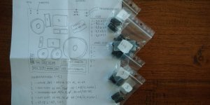
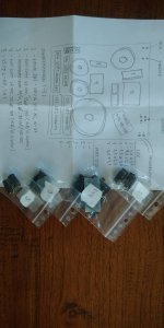
Well, amazingly enough the new Jantzen capacitors arrived this morning! Waaay sooner then I expected.
First thing I did was matching the numbers with the sheet I made earlier...so to avoid silly 'mixup' mistakes. Thanks to the sheet I know where to place the new capacitors.
Has the glue any other purpose then keeping them in place while soldering? Like maybe avoid vibrations when speakers are in action?
Now going to prepare for soldering the new capacitors in place...
Attachments
Hmm, yes, that's also a way of doing it. As I have still some transaprant, flexible and thick construction glue lying around I think I will choose that option. It's quite thick so if I attach it to the board and I add the capacitors I can instantly solder. Thanks for input.I second bicefalo's suggestion of a flexible adhesive. I've used double-sided sticky foam pads as a convenient, non-messy way to secure capacitors to circuit boards in advance of soldering their leads.
This is actually the intention. On the 'dedicated to the Philips FB-820 speakers' forum, persons describe the bridging of the PTC as the sound becoming more 'open', as if a thin curtain lifts from the overall sound image. And I can relate to that as the FB-820 have a nice balance but are 'soft'sounding in the mid/high; nice, but I'm not afraid of giving it that little 'boost'. I'm happy the effect is confirmed here. Now I simply need to wait if it suits me or not. But I'm pretty confident it will. Thanks again for input, I was not completely aware that the effect is caused by the resistor values. Now understand somewhat better.If the tweeter does happen to sound over bright after your renovation, simply remove the PTC (and your link!) and wire a 0.5 ohm, 5 watt resistor in its place.
Thanks for warning and input on this. See #46.No need to say that You have to adjust the tweeters resistors value to compensate for that.
If not your LS will sound brither than before and not due the new components.....
Before you replace capacitors that may well be OK, buy one of these https://www.peakelec.co.uk/acatalog/esr70-capacitor-esr-meter.html . One of the best bits of test gear I've shelled out for.
Has the glue any other purpose then keeping them in place while soldering? Like maybe avoid vibrations when speakers are in action?
The capacitors should be held firmly in place in order to prevent them vibrating to the music.
In the case of large capacitors, this can be done by using plastic ties or glue. In the case of small capacitors, the tension in the soldered leads is usually sufficient to hold them firmly against the PCB.
In the industrial solder flow process, capacitors are glued to the PCB to hold them in place while the process takes place.
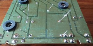
Well, so far so good. I drilled the small holes free of tin (tin still covering some holes after removal of the old capacitors) and I was then able to fit the new Jantzen capacitors, which are smaller versions of the old ones. I used a transparant construction glue to hold them in place and then waited for some 24 hours for it to dry.
Next, the soldering went amazingly well with all the tin dots bright and shiny and connecting well to the board. Finally the cutting of the capacitor wires and I can now hardly tell I did the recap job. This was nice to do! The thing that worked for me was taking my time for the job; no rush.
First thing I will do now is fit the crossovers back in the cabinet so that I can start thinking about adding the damping material, in my case, rockwool.
Can't wait to hear my speakers again soon...they start to feel kind of new to me 🙂
Attachments
Now that the crossoverfilters are new and ready to be re-installed into the cabinet I've now started to add new damping material.
I treat both speakers equally regarding the amount and where/how I place it. I've added a pretty amount of the rockwool as the cabinets from factory were rather empty with only some basic damping material. Describing the amount, I would say I'm filling the entire cabinet about 60% (it was maybe 5-10%) with trying to apply no pressure to the rockwool; except for the sides...to keep it in place. I've also covered the plastic housing of the mid-toner with rockwool...just a gut-feeling.
I keep the space in between both woofers 'open' so that the y stay 'connected' well inside the cabinet. But this is based more on my feeling...that they serve as one big woofer, staying well synchronized.
One of the coming days I will re-install the crossovers and then...well, I guess it's time for a first sound-check 🙂
By the way; I'm keeping the part clear of rockwool where the crossover is placed. Is it okay to cover the crossover with some rockwool or will it give possible problems with heat dissipation? Not sure myself. Input appreciated; also about the way I choose to fill the cabinet.
Attachments
Is it okay to cover the crossover with some rockwool or will it give possible problems with heat dissipation?
There shouldn't be too much heat generated by the crossovers at domestic listening levels, but it is a sensible idea to give them breathing space.
I've no argument over your idea of keeping the damping material clear of the woofer combination. Remember, sometimes less is more!
You may not be familiar with the "Click Test" which can be used to provide an audible indication of when the damping density is optimum.
Here it is courtesy of GM and planet10:

Here it is courtesy of GM and planet10:
The crossovers are back in the cabinets. I've added some more rockwool around the boards but I leave them free so that heat will never be a problem.
Now it's waiting for the glue to dry (used to cover the small hole to put the mid-toner cable thru in its own, small housing) and then I will re-insert the speaker units. Can't wait for the first sound-check!
With the new Jantzen capacitors and the added rockwool damping these 32 year old speakers feel like new and finally treated well.
Attachments

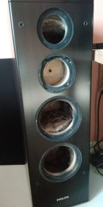
So, this morning I re-inserted and reconnected all the speaker units in both cabinets according to the pictures and drawing I made of the wiring.
However, the first sound-check, carefully performed on low volume, was a dissapointment. Not soundwise, because I think I've made a mistake somewhere.
To describe the problem in the best way: it's as if I've switched the mid-tone and tweeter cable; so, the hi frequencies seem to come from the mid-toner and the mid-frequencies from the dome tweeter. I'm pretty sure that the cables to the tweeter and mid-toner are correctly connected. In my case; the mid-toner cable is marked green on the +wire and the tweeter cable is marked yellow on the +cable.
The woofers sound good. I re-checked the wiring on my drawing, where I made a note of which cables go where and I've also re-checked all the new capacitor values being in the correct place. They are all bipolar by the way.
I've also checked + and - connections to the speaker units themselves and last, re-checked the speaker terminals on +/- connection.
What could be wrong?
I've attached my drawing, where I made a note of the ' MID' and 'TWEETER', with these being the outputs to the mid-toner and tweeter.
On the board the 'TWEETER' connection has the yellow labeled cable and the 'MID' connection has the green labeled cable. So, this is how I reconnected them.
Still, when I put my ear right in front of the mid-toner and/or the tweeter, the high frequencies come from the mid-toner while the dome tweeter has the mid-tones. I'm sure of this.
I'm also aware, from another forum, that the mid-toner is ' out of phase' , so, +/- switched. But as this is done on the board itself I made sure to re-connect the mid-toner as originally done, + to + and - to - terminals.
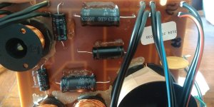
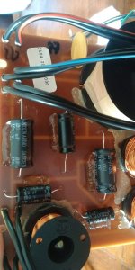
I've added pictures of the board underside and the upper side with new capacitors on it, in case any of you guys might be able to pinpoint the possible problem or (silly) mistake I've made(?).
Sidenote:
I have bridged the PTC resistor but this should not cause any issue, maybe only a little bit more pronounced high frequencies.
The stupid thing is I did make pictures of the wiring when I first started the project, but NOT of the two wires going to the mid-toner and tweeter.
Of course I should have done so.
So now my first doubt is: Did I wrongly indicate the mid-toner and tweeter cable on my drawing, therefore switching them now? Like having a blind-spot...seeing what I want to see when I made the drawing.
Anyway, it should not be a big problem but for now I will await your possible input on this. Maybe you guys know what the problem is(?)
Thanks for any input and help. My last moment struggles to finish this project.
However, the first sound-check, carefully performed on low volume, was a dissapointment. Not soundwise, because I think I've made a mistake somewhere.
To describe the problem in the best way: it's as if I've switched the mid-tone and tweeter cable; so, the hi frequencies seem to come from the mid-toner and the mid-frequencies from the dome tweeter. I'm pretty sure that the cables to the tweeter and mid-toner are correctly connected. In my case; the mid-toner cable is marked green on the +wire and the tweeter cable is marked yellow on the +cable.
The woofers sound good. I re-checked the wiring on my drawing, where I made a note of which cables go where and I've also re-checked all the new capacitor values being in the correct place. They are all bipolar by the way.
I've also checked + and - connections to the speaker units themselves and last, re-checked the speaker terminals on +/- connection.
What could be wrong?
I've attached my drawing, where I made a note of the ' MID' and 'TWEETER', with these being the outputs to the mid-toner and tweeter.
On the board the 'TWEETER' connection has the yellow labeled cable and the 'MID' connection has the green labeled cable. So, this is how I reconnected them.
Still, when I put my ear right in front of the mid-toner and/or the tweeter, the high frequencies come from the mid-toner while the dome tweeter has the mid-tones. I'm sure of this.
I'm also aware, from another forum, that the mid-toner is ' out of phase' , so, +/- switched. But as this is done on the board itself I made sure to re-connect the mid-toner as originally done, + to + and - to - terminals.
I've added pictures of the board underside and the upper side with new capacitors on it, in case any of you guys might be able to pinpoint the possible problem or (silly) mistake I've made(?).
Sidenote:
I have bridged the PTC resistor but this should not cause any issue, maybe only a little bit more pronounced high frequencies.
The stupid thing is I did make pictures of the wiring when I first started the project, but NOT of the two wires going to the mid-toner and tweeter.
Of course I should have done so.
So now my first doubt is: Did I wrongly indicate the mid-toner and tweeter cable on my drawing, therefore switching them now? Like having a blind-spot...seeing what I want to see when I made the drawing.
Anyway, it should not be a big problem but for now I will await your possible input on this. Maybe you guys know what the problem is(?)
Thanks for any input and help. My last moment struggles to finish this project.
Attachments

The obvious thing to do is to try swapping the wires going to the mid and tweeter to see if that resolves the problem.
Once you’ve sorted and confirmed your connections, keep in mind that one of the things that usually happens to older electrolytic crossover capacitors is that they will gain capacitance. This changes the function and sound…
This may be an adjustment if you have been using the speakers in a well used state.
This may be an adjustment if you have been using the speakers in a well used state.
Last edited:
Electrolytic capacitors that don't dry out, but only see a small applied voltage for some time, can suffer an increase in capacitance
On the other hand, electrolytic capacitors that do dry out over time can suffer a decrease in capacitance.
It's all a bit of a lottery!
Fresh electrolytics will likely give a slightly different sound balance to which one's ears will adapt over time.
On the other hand, electrolytic capacitors that do dry out over time can suffer a decrease in capacitance.
It's all a bit of a lottery!
Fresh electrolytics will likely give a slightly different sound balance to which one's ears will adapt over time.
- Home
- Loudspeakers
- Multi-Way
- Specs new capacitors for crossover filter