Thanks for the tip. Wonder what others are doing for these parts. Anyway ordered relays that had the same pin out and coil ohms and measurements to the holes in the board. From China so maybe by this fall will get parts?? Thanks again and stay safe.
One just has to do a little digging. Look at old parts specs and see what new part will work. Mouser also recommends new, alternative parts when you look at the obsolete part’s information.
Pete
Greetings all,
Would the basic circuit in the amp DC protector also function at the line level (0 to 2v)? I need DC protection in my all-balanced signal chain. I believe my balanced amps are solid, and that the rare source of DC comes from misbehavior by a microprocessor. I can lay out miniaturized circuits, but I'm not an engineer to understand the detection side of the equation.
Would the basic circuit in the amp DC protector also function at the line level (0 to 2v)? I need DC protection in my all-balanced signal chain. I believe my balanced amps are solid, and that the rare source of DC comes from misbehavior by a microprocessor. I can lay out miniaturized circuits, but I'm not an engineer to understand the detection side of the equation.
Greetings all,
Would the basic circuit in the amp DC protector also function at the line level (0 to 2v)?
I just found the headphone amp protection circuit at AMB so am no longer in need of help. Stay healthy, everybody!
Thanks as I did some digging but well enough. When original part came up a suggested new part number came up but the pin out was incorrect. So I stopped there. Thanks for the tip.One just has to do a little digging. Look at old parts specs and see what new part will work. Mouser also recommends new, alternative parts when you look at the obsolete part’s information.
Pete
Thank-you for the tip.Look to Mouser part # 653-G5LE-1-DC12
Cheers, Pete
I am putting together a fairly stock F5 build with soft start and speaker protection. My transformer is 500VA 18V+18V.
I'd prefer to not add another transformer or PSU for the speaker protection board if possible. I know the BOM lists 5V and 12V relays (for 24V and 12V input), so the coil voltage is roughly half the input voltage.
Since I have 18V secondaries would it be appropriate to use two G5LE-14 DC9 (9V)? Note that (IIUC) the G5LE-14-DC5 and G5LE-14-DC12 are modern equivalents (5V and 12V) of the out of production relays in the BOM.
If the G5LE-14 DC9 is suitable I think it would be very helpful to add this part to the BOM as an option for builds with 18V secondaries. Also, it would be great to update the BOM with current part numbers since questions about the EOL ones have come up in this thread a few times.
Last edited:
if your transformer only has one set of 24VAC secondaries. If the transformer has two separate secondary sets (one being ~24VAC) you’re in (semi) good shape.
I Have an amp with 2x24vac secondaries. I'd like to power up the board witht that but I don't get how it can be made. With center tap, you just put the 0v side to ground. With mine, how doe one do that? Would you mind e=developping on that? I can't find any har dinfo on that matter anywhere.
Othersise, I'l just buy a simple center tapped transformer like others have done.
Can't you just connect the speaker protection board to one of the 24V secondaries and then use 12V relays?
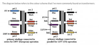
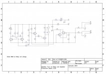
I’ve attached the schematic of the V3 Turn-on delay and protection board. The voltage inputs are U1.1 & U1.2 (I think it’s a "U"...could be a "V"). The board can be driven either by AC directly or DC if you wanted to (U1.2 is +DC and U1.1 is the common return (call it the "-" side if you’d like)). I’ve also attached a common picture of a toroidal type transformer with 2 separate input primaries and two separate output secondaries. I’m presuming you have this type of transformer and 120VAC mains?
So to drive both secondaries with xxVAC output (let’s say 24VAC) you would connect the transformer as is shown on the pic on the right (blue & violet wires are joined together as are the grey & brown; colors may vary depending who makes the transformer). You can hook up each of the joined pairs to either the mains live (black wire in USA) or the Common return (white wire in the USA). Doing it like the picture blue+violet are connected the the mains "common/white wire" and grey+brown are connected to the mains "Live" or black wire. So now the secondary outputs black & orange become the "Common" returns for their respective red & yellow "24VAC mains Live". So you would take one of those 24VAC pair (let’s say the black & red pair) and the red can be connected to the U1.2 line and the black to the U1.1 line (it doesn’t matter with AC but D6 would match up the "+" side of a VdC input so just by convention, on my part, I make that the Mains "live" side of the AC in).
I just prefer to use a AC to DC voltage regulator to drive the board to get a clean, constant voltage into the protection board.
Does that answer your question?
Cheers,
Pete
Attachments
Having just said all that, when is used the board I had to drive it with it’s own separate transformer since both of the secondaries out of my toroidal were being used to drive the two amp boards for L & R stereo outputs in my amp and wanted those secondaries solely driving the amps.
What is the minimum VA value of the supply transformer?
See post #52
Having just said all that, when is used the board I had to drive it with it’s own separate transformer since both of the secondaries out of my toroidal were being used to drive the two amp boards for L & R stereo outputs in my amp and wanted those secondaries solely driving the amps.
A few pages ago you mentioned using a Mean Well RS-15-24 to power the board. Did you change that in favor of a separate transformer like you mentioned here?
I'm still trying to weigh power options for my F5 build with 18v secondaries:
1) 18v secondary and use 9V relays
2) universal PSU +24Vdc
3) Mean Well RS-15-24 supply or similar
4) second 24V 10VA transformer
Option 1 is probably the easiest, and since the board would be powered by AC it would open the relays before the amp boards powered down (no thump).
Option 2 is easy but has the problem of speaker thumping on switch off because the board would remain powered along with the amp while the PSU caps discharged (earlier posts in this thread mentioned this problem).
Option 3 seems doable but I am not sure if the second PSU would introduce noise, or if it requires its own (lower rated) fuse.
Option 4 is tricky for me since I am having trouble sourcing a transformer. I am in Spain and I seem to be able to get a reputable brand or a decent price but not both! The Antek 0124 is almost 50€ shipped, and the Triad can't be shipped to Spain according to Mouser.
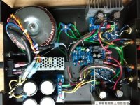
No, I used the Mean Well for one project (see the picture; mean we’ll mounted on its side). I also used a separate center-tapped transformer & AC/DC regulator on another project (a speaker protect board kit I bought on EBay cause I had a bit more room and extra parts laying around. Attached is a photo of the DIY board and the Mean Well. The switching power supply lies outside the signal path (it only powers the relay coils) and draws power directly from the mains input to the amp (which is fused) and connected to a mains on/off switch on the chassis. I didn’t get any hum through the amp but I’ve also got everything grounded.
I’m sure the 12V relays would work fine with the secondaries in choice #1. And with option #2, you are correct about the thumping issue. I learned that too.
Cheers,
Pete
I’m sure the 12V relays would work fine with the secondaries in choice #1. And with option #2, you are correct about the thumping issue. I learned that too.
Cheers,
Pete
Attachments
Last edited:
See post #52
I would think that the minimum size transformer required would be pretty small - a lot less than .25 amp. I need to try but wouldn't something like a little 2VA
transformer work?
Probably so but it's overkill and the transformer probably would be bigger and take up more space. Look to the spec sheets for the relays to see what the tolerance range is (and recommended values are).
Having just said all that, when is used the board I had to drive it with it’s own separate transformer since both of the secondaries out of my toroidal were being used to drive the two amp boards for L & R stereo outputs in my amp and wanted those secondaries solely driving the amps.
Thanks for the detailed description. But I understand all of this. THe thing is, my 2 transformer secondaries drives, just like yours, my 2 channels. And it's the grounding part that puzzles me (nex tto D6). Even If I decided to use one of my secondaries, whre is the ground connection supposed to be made, physically?
MartyBoy...this is my understanding of those symbols on a schematic. More learned electrical folk can correct me. The ground symbols on the schematic do not represent chassis grounds (like the green wires you can see in my picture). They do represent earth grounds. The ground symbols (like next to D6) just represent the connection to the "Common" AC line/path on the board, e.g., the wire connection from a secondary transformer output generally marked as "zero VAC" or the (-) negative line from a DC input source).
You might only need to "chassis" ground the speaker protection board if it is inducing a hum in the output.
You might only need to "chassis" ground the speaker protection board if it is inducing a hum in the output.
Last edited:
- Home
- The diyAudio Store
- Speaker Turn On Delay and DC Protector Board Set (V3)