Probably so but it's overkill and the transformer probably would be bigger and take up more space. Look to the spec sheets for the relays to see what the tolerance range is (and recommended values are).
The point I was trying to make is that for a transformer to output 250mA at 12volts would be rated 3VA and at 24V it would be rated at 6VA which may require a larger transformer than the 2VA transformer I was asking about.
I am a total noob so maybe I am missing something.
No, your calculations are correct. I should have looked at your question more carefully. Sorry, my apologies. The quoted 250mA is a estimation and you can probably go lower than that.
The Antek AN-0124 is a 10VA toroidal and works just fine on this board (it’s tiny and looks like a toy). So parallel the primaries (for 115VAC in) which means each independent 24V secondary is 10VA/2 =5 and 5/24 = 0.21A at 24VAC. For a transformer with one primary and one secondary (24VAC) a similar 0.21A output calculates to a 5VA transformer.
A G5LE relay’s coil (12V) has a rated current draw of 33.3 mA but can handle more A 2VA 24VAC transformer (if a single secondary) should output 83 mA if there are no mains voltage fluctuations. You were correct...you’re living life on a fine edge with the 2VA transformer (but it may work). My Mean Well RS-15-24 put out 24V at 625mA (a comfortable margin).
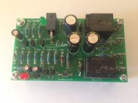
No, I used the Mean Well for one project (see the picture; mean we’ll mounted on its side). I also used a separate center-tapped transformer & AC/DC regulator on another project (a speaker protect board kit I bought on EBay cause I had a bit more room and extra parts laying around. Attached is a photo of the DIY board and the Mean Well. The switching power supply lies outside the signal path (it only powers the relay coils) and draws power directly from the mains input to the amp (which is fused) and connected to a mains on/off switch on the chassis. I didn’t get any hum through the amp but I’ve also got everything grounded.
I’m sure the 12V relays would work fine with the secondaries in choice #1. And with option #2, you are correct about the thumping issue. I learned that too.
Cheers,
Pete
Thanks! I wish I could get a tiny toroidal 10VA like that Antek but shipping to Spain is way too expensive. The European transformer companies I have found only make 20VA and up, quite a bit larger! Since it's not powering audio circuits I can probably get something from eBay, but who knows what kind of EM noise it will create in the chassis!
rsaumure: does your 2VA transformer have dual secondaries, each outputting 24VAC or is it a simple step down transformer with 115VAC in and 24VAC out? I tried reading backwards but couldn’t find that info.
Thanks
Thanks
Do I understand correctly the speaker protection board runs equally well from AC or DC?
Other than for simplicity or what one has on hand, is there a compelling reason to go one way or the other?
Other than for simplicity or what one has on hand, is there a compelling reason to go one way or the other?
Schematic
Hi,
Where can I see the schematic?
Regards,
Sumesh
Hi,
Where can I see the schematic?
Regards,
Sumesh
This thread is for discussions about the new Speaker Turn-On Delay and DC Protector boards (V3). This is an updated version of the V2 boards, primarily to make them compatible with the 10x10 grid mounting pattern we've now standardized on so they can be easily mounted to Deluxe chassis baseplate, riser panels, front panels and/or heatsinks. Refer to the V2 discussion thread for additional information.
For more information on this product, please see the product page.
Change History
- 2.0 First Production Release
- 2.0.1 Added Board Dimensions
- 3.0 New Layout
- Double sided board
- Added Keystone connectors as option
- Conforms to 10mm mounting grid
- For future changes
- Add polarity markers for electrolytic capacitors
Information
- Product Page
- BOM - Attached below (Now updated to V3.0.2) -- 3-paged BOM
- Schematic - Coming soon
- Dimensions - 100mm x 50mm
I created a couple projects on Mouser to help with easy ordering.
12VAC supply: Mouser Electronics
24VAC supply: Mouser Electronics
12VAC supply: Mouser Electronics
24VAC supply: Mouser Electronics
\I created a couple projects on Mouser to help with easy ordering.
12VAC supply: Mouser Electronics
24VAC supply: Mouser Electronics
Is this for one speaker or two speakers?
\
Is this for one speaker or two speakers?
They're based on the standard BOM which is for 2 speakers unless I'm mistaken.
I am trying to incorporate this board into my honey badger build. I have an AN-6440 - 600VA 40V Toroidal Transformer it has 12 and 18 V windings. I want to hook the board up to the 18 VAC winding. How does this board reference ground in that case?
VV, damn man, I just got down building one and all I had to do is wait one day and I have just clicked. lmao
Ah well... thanks for posting for the next guy. Did you do one for the soft start? That's the next one I have to do
Ah well... thanks for posting for the next guy. Did you do one for the soft start? That's the next one I have to do
Trace Elliot Acoustic Amp
Ran across as I was searching for a way to prevent my Trace Elliot TA60CR from making a loud popping sound during power down. Would the Soft Start module do the trick? Would I install this unit between the amp and speakers?
Thanks
Ran across as I was searching for a way to prevent my Trace Elliot TA60CR from making a loud popping sound during power down. Would the Soft Start module do the trick? Would I install this unit between the amp and speakers?
Thanks
Ran across as I was searching for a way to prevent my Trace Elliot TA60CR from making a loud popping sound during power down. Would the Soft Start module do the trick? Would I install this unit between the amp and speakers?
Thanks
You are looking for the speaker delay board... it protects from turn on and off transients. I can't say if it will work, or not, I haven't built one yet hopefully someone else will chime in...
Last edited:
You are looking for the speaker delay board... it protects from turn on and off transients. I can't say if it will work, or not, I haven't built one yet hopefully someone else will chime in...
TTs is correct..you want a speaker turn delay relay circuit not a soft start. If you buy it from the DIYAudio store the speaker delay and soft start boards are sold as a pair (but you can obviously use them independent of one another). I’ve used both boards in an amp build. Speaker delay works fine but needs to be driven by a small, second transformer. My only complaint about the speaker delay board is that it’s not very compact.
Cheers, Pete
Thanks for the reply. This looked like an overkill for this amp. I am also looking at a simpler option: hanging a .1uF across(one side + other side -) the big filter caps in the PS. I believe that Peavey does that to their solid state amps.
I have a separate 7VA transformer to run this speaker protection board but am a little confused about how I reference this to my amplifier 0v for the DC protection to work?
Do I just power this board directly from the 7VA transformer and then take a link from the 0v in to my star ground in the amp? (star ground is connected to the PSU 0v via a CL60)
Do I just power this board directly from the 7VA transformer and then take a link from the 0v in to my star ground in the amp? (star ground is connected to the PSU 0v via a CL60)
Sigh. Out of stock in the store. Any idea when they will be available again? How about the DXF files for the boards?
Negative DC not triggering protection?
I just rebuilt my F5 after some big changes and thought I'd test a few things before putting it back in use.
To test the speaker protection I used a small 2x AAA battery holder and touched the negative lead to the terminal marked G (I think?) and the positive to IN1. It did what was expected and opened the relays for a few seconds.
I decided to also test negative DC, so I swapped the battery holder leads. This did nothing after several seconds.
3V seems like it should be plenty to test DC protection -- and clearly is for positive DC. I would have assumed the board would protect against negative DC. Did I assume wrong? Has anyone else tested this and found the same or different results?
If it matters, I am driving this straight from a dedicated 24V (15VA?) transformer, so I am using the onboard rectification. The G terminal is connected to one secondary and also audio/PSU ground (floating from chassis ground). The other terminal is only connected to the other secondary.
Last edited:
If you look at the schematic, positive voltages on the speaker terminal drive the base of the sensing transistor. Negative offsets connect to the emitter of the sensing transistor and, therefore, do not have the benefit of the transistor current gain so negative offsets have to draw sufficient current through resistor connected to the collectors of the sensing transistor to turn the relay drive transistor off. It simply takes a higher offset than the positive direction.
- Home
- The diyAudio Store
- Speaker Turn On Delay and DC Protector Board Set (V3)