Hello, everyone.
Can this speaker delay DC protector board be used stand alone DC blocker? My amp already have speaker relay installed by someone and it has slight toroidal hum. I guess that it is bad DC getting into the amp.
Hence, I just got this DC protection board but not sure if it can be used as stand alone DC blocker by having separate case and AC Main plug on both ends so amp connect to one end and the other end is connect to wall socket. Sorry for asking newbie questions.
Resurrecting the diyaudio's own speaker turn on delay & dc protection circuit...
- Does this circuit latch when dc fault is detected such that a power cycle is needed ?
- I presume R7 (or C3) controls the start up delay. To get about 10 seconds delay,
would increasing R7 to about 250k work ?
- Does this circuit also have a way of cutting out the speaker as soon as the a/c power
is shut off (to avoid turn off thumps) ?
- What is the dc power requirement to run the circuit ?
- How quick is the detection time when the dc is detected at about 30 volts ?
Thanks
Connection questions
Hello
I‘m not sure about the connection of the speaker delay board—signal connection is amp-out -> in1 then spk1 -> speaker post, right.
But for power (G and +V), do I need a separate transformer (or, is it better practice), or can I highjack the current from the main transformer‘s secondaries (which are supposed to deliver clean electricity to the amp-boards)?
Thank you!
Power to the speaker protector board
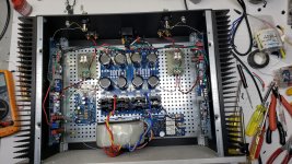
If the main transformer is in a Firstwatt amplifier you can use the main transformer. The AC side of the Diy store power board AC1A or AC1B can be run to the speaker protector board. The return path for the board will be tied to the power supply board ground. I went with external relays and wired the common switch contact to the speaker posts , the N.C. contact to the speaker ground and the N.O. contact to the output of the Amplifier board as recommended by Elliot ( Loudspeaker Protection and Muting ). This connection saves the speaker at the expense of the relay. It is my understanding that a shorted output transistor placing full rail voltage on the speaker will cause the contacts in the relay to arch and possibly cause the contacts to weld closed. This system has worked well for two years now.
If the main transformer is in a Firstwatt amplifier you can use the main transformer. The AC side of the Diy store power board AC1A or AC1B can be run to the speaker protector board. The return path for the board will be tied to the power supply board ground. I went with external relays and wired the common switch contact to the speaker posts , the N.C. contact to the speaker ground and the N.O. contact to the output of the Amplifier board as recommended by Elliot ( Loudspeaker Protection and Muting ). This connection saves the speaker at the expense of the relay. It is my understanding that a shorted output transistor placing full rail voltage on the speaker will cause the contacts in the relay to arch and possibly cause the contacts to weld closed. This system has worked well for two years now.
Attachments
this one[/URL] is not as tall
Moin Freiheit
Thanks for the pointer!
This little bug would be nice, but.
It is still 2 times what is needed (the speaker protection board needs something like 1A / 12 VA, according to mighty ZM)
Also, I received a reply stating that the relays + the little stuff on the board would need just about 125 mA or so, that is around 1.5 VA.
A small onboard tranny like this one (EI305 2874 Leiterplatten-Transformator 2.3 VA 24 VAC Hahn ) should be good. Half the price, half the size, but more effort needed for the construction... and since I already smoked one of them, I should get it working this time [emoji51]
David, thank you for the explanation.
The one you have your eye on suits your specs much better. I had a search but have not come up with anything better. In fact, most transistors that size seem to a lower voltage specification for the secondaries, so congratulations on finding that one!
Good luck for not frying it this time 🙂
The one you have your eye on suits your specs much better. I had a search but have not come up with anything better. In fact, most transistors that size seem to a lower voltage specification for the secondaries, so congratulations on finding that one!
Good luck for not frying it this time 🙂
David, thank you for the explanation.
The one you have your eye on suits your specs much better. I had a search but have not come up with anything better. In fact, most transistors that size seem to a lower voltage specification for the secondaries, so congratulations on finding that one!
Good luck for not frying it this time 🙂
I‘ll prepare my breakfast (sunny side up) before just in case [emoji28]
For the love of God please update the BOM on page 1! Six years and it still hasn't gotten done.
I know there are version, but just dump the PDF version 3 off there please.
What's worse is I caught it ordered the right ones then put the damned wrong one in. GAHHARRRR!
I know there are version, but just dump the PDF version 3 off there please.
What's worse is I caught it ordered the right ones then put the damned wrong one in. GAHHARRRR!
Last edited:
Installed on Honey Badger did not protect speaker
I had built and installed the protection board in my honey badger build, the honey badger was working fine until one day I powered it up and it blew the fuse on the left channel, also caused a large pop, long and short I lost the channel and it blew out the woofer on the left speaker.
When I built this board, I also ordered the KSC945 from the incorrect BOM, I had issue with the start up. I replaced those transistors with 2N2222, all worked fine.
BUT, it failed to provide protection on start up one time and caused the loss of the speaker.
Is there a test on which can be conducted to insure the circuit is working other than the leds going solid on start up. It functions with no issue in connecting the speakers after delay, however I am not sure the DC protection is working correctly.
Suggestions would be appreciated, I have fixed the Honey Badger found a bad transistor and resistor and replaced and got it all working, now I have to fix the speaker unfortunately this was a Sonus Faber and the damn speaker company will not give you any information they want you to send them in which is costly.
I will fix the speakers, but I want to avoid this in the future, the Honey Badger does not have an overload protection circuit in the design, which is an issue.
Testing the board
I tested my board before installing. With power applied to the board I placed a 9 volt battery across the speaker input to the board. The relay should open . I then reverse the polarity of the battery. The relay should the open. I would suggest reading Rod Elliot's article on the subject. Loudspeaker Protection and Muting. pay attention to the relay failure due to arc.
I tested my board before installing. With power applied to the board I placed a 9 volt battery across the speaker input to the board. The relay should open . I then reverse the polarity of the battery. The relay should the open. I would suggest reading Rod Elliot's article on the subject. Loudspeaker Protection and Muting. pay attention to the relay failure due to arc.
Thanks
I did read that article was going to order a couple of his boards the shipping was too high.
What transistors did you end up using in the dyiaudio circuit ?
I did read that article was going to order a couple of his boards the shipping was too high.
What transistors did you end up using in the dyiaudio circuit ?
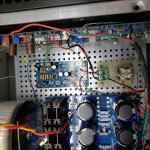
I used the BC546C in place of the 2SC945 for T3,4,5 and the 2N2222A ( metal case ) in place of the T6 2SC9013 , T1,2 are 2N4400. Be aware of the pinout , they are not the same. I went off board with the relays for two reasons. I could place a larger relay in line with the speaker wire, and two I could wire the speaker to the common of the relay, and the ground to the normally closed . If the relay were to arc hopefully most of the energy would flow to ground and not through the speaker. I did relocate LED 1 to the front panel. The circuit has worked well with the Aleph J .
Attachments
I don't have any faith in the board, when I did the test per the instructions it took a second or so to disconnect.... a second and the speaker is toast. I'm now looking for another solution.
I am using Rod Elliot's circuit in my 160 watt per channel bipolar subwoofer amp with no problem. There are quite a few more parts in it . I built the circuit on my own hand etched P.C. board.
I don’t have faith in the board as well
I am looking at getting elliots boards as well this dyi audio board failed and it should have not connected on power up as it did.
I am looking at getting elliots boards as well this dyi audio board failed and it should have not connected on power up as it did.
J, I appreciate your input as the designer, but we have a diy product in the store, that offers limited/no protection. One second of DC kills drivers. I used a 9v on some cheap speakers and they damned near jumped out of the box before the relays engaged. I am not a designer , but I look at the data.... the data told me to discard the circuit utterly.
PS I built 2 boards, if anyone wants them, they are yours, just pay for the boards and the parts....
PS I built 2 boards, if anyone wants them, they are yours, just pay for the boards and the parts....
Last edited:
Request for review by the mods/designers, please
Good morning and happy 21 everyone!
I would like to ask for toecutter (the board designer?), jason (the store-„manager“?), or some other person involved in this project to drop into this discussion.
Thompsontech says this board does not work as intended, and I am far from capable to verify this. My gut-feeling tells me that it would be strange that a faulty project exists/survives/is sold some 8 years, but on the other hand this very thread seems to be a bit abandoned...
@thompsontech, I am not questioning your knowledge, but could it be that a hardware-bug creeped in while you were struggling with the faulty bom and availability-issues? This is the question I would inquire the mods to examine and to verify wether the board indeed is doomed or not...


Thank you!
David
Good morning and happy 21 everyone!
I would like to ask for toecutter (the board designer?), jason (the store-„manager“?), or some other person involved in this project to drop into this discussion.
Thompsontech says this board does not work as intended, and I am far from capable to verify this. My gut-feeling tells me that it would be strange that a faulty project exists/survives/is sold some 8 years, but on the other hand this very thread seems to be a bit abandoned...
@thompsontech, I am not questioning your knowledge, but could it be that a hardware-bug creeped in while you were struggling with the faulty bom and availability-issues? This is the question I would inquire the mods to examine and to verify wether the board indeed is doomed or not...
Thank you!
David
I did not say it is faulty, I said it doesn't react fast enough for my use. Hell, I might have something wrong, it could be anything, many have used the boards and I don't see a lot of complaints. I just ran the test as in the build guide and it took to long, in my opinion. I tried it again on some junk speakers and the result was such that I would never attach it to a good pair of speakers.
Last edited:
- Home
- The diyAudio Store
- Speaker Turn On Delay and DC Protector Board Set (V3)