relays open after ~2.8 sec
8V 1.9A doesn't trip... 😕
So first questions are whether you have built this using the official boards?
The initial delay is given by the R/C time constant of R6 and C3 and the need for the voltage to rise on C3 to equal and exceed the Zener voltage. When that happens Q6 turns on.
If your board isn't behaving correctly then we can troubleshoot it just as we would any other design.
Mooly, thanks for helping me looking into it.
The board is from the store, purchased march 2020.
Parts are according to the BOM 3.0.1
I should crosscheck the whole build for differing parts I guess, will do in the coming days (day-job has begun again)
...
Haven't connected it to the amp yet (f4 which is not finished but close)
The board is from the store, purchased march 2020.
Parts are according to the BOM 3.0.1
I should crosscheck the whole build for differing parts I guess, will do in the coming days (day-job has begun again)
...
Haven't connected it to the amp yet (f4 which is not finished but close)
You're very welcome 🙂 and thanks.
The time taken for the circuit trip is determined by the voltage on R11 exceeding - or + 0.7 volts approximately. When that happens either Q4 or Q5 will turn on (depending on offset polarity) and turn the relays off.
So the factors effecting this are the time constant of the two 330uF caps and the 27k feeding them.
If the time constant is made to small then the circuit will trip on wanted high voltage bass notes. So it is a compromise (as all these type of circuits are, it is not unique to this one).
So the 330uF caps can be reduced and that will decrease the trip time. I would not recommend increasing the 27k's because these are needed to allow sufficient base current for the trip transistors to be available in the event of a true fault.
Fitting 100uF caps for example now gives a trip time of just over 60 milliseconds.
Given that we normally listen to just a few volts in output there is no harm in reducing these caps if you feel you want faster protection.
The simulation can also be used to apply a low frequency input voltage and so allow a determination of when the circuit might trip. High frequencies are filtered by the R/C time constant, it is the bass that is the problem.
Lets try 20Hz at 40 volts peak. So that is the nominal 50 watts rms/8 ohm value. And it seems fine with just 100uF caps fitted. You can see the relay trace in red.
Lets go to 47uF. And that shows the circuit now will not close the relay. The signal itself is tripping the circuit... but that is 50 watts worth of signal at 20Hz.
So I would by all means experiment. The worst that can happen is the relay trips when you turn up the volume and there is lots of bass.
And Happy New Year folks
Arent those two 330 uF caps actually a 115uF bipolar ? They seem like connected back to back to make it bipolar.
Definitely do a component check. Also make sure the DC supply is correct which I think is around 12 to 15 volts DC on C6.
If you remove (or lift one end) of R10 and D5 then you remove interaction with other parts of the circuit and you should see the basic delay of around 10 seconds.
That could be a good test as it eliminates a lot of possible interactions and leaves just the basic R/C time delay with nothing to alter it.
Arent those two 330 uF caps actually a 115uF bipolar ? They seem like connected back to back to make it bipolar.
Yes, they make a bipolar type cap which is needed because any offset could be of either polarity.
Mooly, thanks for helping me looking into it.
The board is from the store, purchased march 2020.
Parts are according to the BOM 3.0.1
I should crosscheck the whole build for differing parts I guess, will do in the coming days (day-job has begun again)
...
Haven't connected it to the amp yet (f4 which is not finished but close)
Actually... make sure the Zener is fitted the correct way around as that would give a much lower time delay if incorrect.
Nothing to add at this point that wasn't already said, which paraphrased was "if a specific test can be documented which doesn't produce the expected result we will investigate without fear or favor", as would always be the case. We're all on the same side here, so please keep discussion on topic so we can get proceed directly to the result, thanks 🙂
Many thanks to Mooly for the analysis so far. Jojo was the boards designer, and is currently on holiday but has let me know he will join in the discussion when he's back should we not get to the bottom of it before then.
Many thanks to Mooly for the analysis so far. Jojo was the boards designer, and is currently on holiday but has let me know he will join in the discussion when he's back should we not get to the bottom of it before then.
Definitely do a component check.
Molly,
I went through the components, by comparison of my mouser order-history, the BOM I used, and my board.
All parts—ZENER too—seem to be correctly placed.
There are 2 differences to the BOM:
Q1 Q2 Q3 Q5 Q6:
Original in the BOM: 512-KSC945CGBU
I have 512-KSC945CYTA — compared the product-info and couldn't find a difference.
K1 K2:
"Original" is obsolete, 653-G5LA-14-CF-DC12 – Switching Voltage: 250 VAC, 24 VDC
I went with 653-G5LE-1VD-DC12 – Switching Voltage: 250 VAC, 125 VDC
This being the outstanding difference, is it... the bug?
The LEDs are from my stash, kingbright something from the B1 mez...
Next for me would be to follow your instructions re:check board...
thanks already many times!
d. )
Also ...
I just switched the transformer (a 24V 2.3VA instead of 24V 10VA) and reconnected the LEDs (they'll end on the front...), hooked it up and powered on.
LED alight, relay trigger after ca 3.6".
Then I inadvertently shorted the LEDs (legs not isolated), which immediately triggered the relays, which came back after those 3.x seconds.
Is this what I should've expected? Am I still required to check for DC in the SPK?
I already feel mo' confident 🙂
The transistors are very non critical in a design like this although you have to watch that the pin outs are correct for any equivalents.
So lets begin by looking why you are not getting the correct delay at power on.
I would suggest you lift one end (to isolate it) of R10 and also D5. This isolates the basic timing generator so we can see what is happening.
First check is to confirm the supply voltage is correct on C6 which is the 220uF reservoir cap.
What voltage do you measure here? Let us see what your supply actually is.
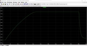
From initial power on you should see the voltage on C3 (47uF) climb slowly and after around 10 seconds it should be pretty close to the Zener voltage of 6.8 volts.
This is an important step. The voltage is shown here and you can see how it climbs and then limits at the Zener voltage.
Check that yours does this (limits at approx the Zener voltage) and that the time to reach this voltage is around 10 seconds.
Note... you must use a DVM for this and not an old analogue type meter whcih would load the circuit down to much.
So that is the first step. Isolate those two parts and check the timing voltage rises at the correct rate.
This is how the voltage on the 47uF cap rises over time.
So lets begin by looking why you are not getting the correct delay at power on.
I would suggest you lift one end (to isolate it) of R10 and also D5. This isolates the basic timing generator so we can see what is happening.
First check is to confirm the supply voltage is correct on C6 which is the 220uF reservoir cap.
What voltage do you measure here? Let us see what your supply actually is.
From initial power on you should see the voltage on C3 (47uF) climb slowly and after around 10 seconds it should be pretty close to the Zener voltage of 6.8 volts.
This is an important step. The voltage is shown here and you can see how it climbs and then limits at the Zener voltage.
Check that yours does this (limits at approx the Zener voltage) and that the time to reach this voltage is around 10 seconds.
Note... you must use a DVM for this and not an old analogue type meter whcih would load the circuit down to much.
So that is the first step. Isolate those two parts and check the timing voltage rises at the correct rate.
This is how the voltage on the 47uF cap rises over time.
Attachments
I just switched the transformer (a 24V 2.3VA instead of 24V 10VA) and reconnected the LEDs (they'll end on the front...), hooked it up and powered on.
24 volts AC will generate a 33 volt rail. That will reduce the timing delay. So you may actually not have a problem 🙂
If you want a longer delay then you can increase the 47uF cap to 100uF.
I just switched the transformer (a 24V 2.3VA instead of 24V 10VA) and reconnected the LEDs (they'll end on the front...), hooked it up and powered on.
The pictures I have seen of the completed board shows 5 volt relays. That would be consistent with a nominal 12 volt supply and a 9 transformer.
Are there any details anywhere detailing the recommended supply voltage range. I've looked but couldn't just see anything.
I was fumbling with my dvm while you wrote those 2 replys. Bet left hand against right hand it is working [emoji847]
@ C6 ≈ 18.6V
@ C3 ≈ 7.6V
R10 and D5 still in place...
Is there a way to get the relays to trip with DC (simulate a faulty amp)?
Thank you so much!
d🙂
@ C6 ≈ 18.6V
@ C3 ≈ 7.6V
R10 and D5 still in place...
Is there a way to get the relays to trip with DC (simulate a faulty amp)?
Thank you so much!
d🙂
Last edited:
So the voltage on C6 suggests your transformer is putting out around 12 volts AC.
C3 voltage sounds good and is actually the Zener voltage plus the two diode volt drops caused by T3 and T6 base/emitter junctions.
So that sounds all good up to now.
The delay time is influenced by the supply voltage. A higher supply means the current in the charging resistor R6 is higher and that charges the cap up more quickly.
If you want a longer delay then try increasing the 47uF cap first. You could try 68uF, 82uF or 100uF.
The relay should trip out when you apply a DC voltage of of 4 volts or more across either of the inputs. It should still trip if you reverse the polarity of the voltage at the speaker input.
A good way to test it is to first of all just connect a 9 volt battery to the speaker input. It should trip which ever way around you connect the battery.
When you remove the battery the relay should engage again after the full time delay set by R6 and C3
I want them to trip!
So here's my roadblock: It doesn't trip.
I apply a pretty much full 9V battery to any SPK / IN combination, it does nothing...
So here's my roadblock: It doesn't trip.
I apply a pretty much full 9V battery to any SPK / IN combination, it does nothing...
Here are some simple tests.
1/ If you apply a short from T4 and T5 collectors to ground then the relay should trip out. Doing this removes charge from the timing cap and turns off T3 and T6
Just short it out momentarily with a bit of wire and see if it trips.
It must pass this test before going further.
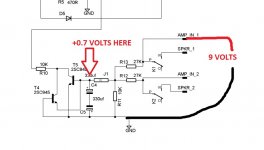
2/ If you apply 9 volts to the speaker in connection then you should measure a DC voltage of around positive 700 millivolts across the two series connected caps C4 and C5.
Remember that the negative of the battery must connect to ground on the board and that the 9 volts must be applied to one of the 'Amp In' terminals.
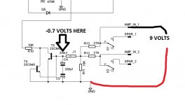
3/ If you now reverse the polarity of the battery then the voltage across the two caps should also reverse and this time measure around negative 700 millivolts.
Lets see where that gets you 😉
I'll look in later.
1/ If you apply a short from T4 and T5 collectors to ground then the relay should trip out. Doing this removes charge from the timing cap and turns off T3 and T6
Just short it out momentarily with a bit of wire and see if it trips.
It must pass this test before going further.
2/ If you apply 9 volts to the speaker in connection then you should measure a DC voltage of around positive 700 millivolts across the two series connected caps C4 and C5.
Remember that the negative of the battery must connect to ground on the board and that the 9 volts must be applied to one of the 'Amp In' terminals.
3/ If you now reverse the polarity of the battery then the voltage across the two caps should also reverse and this time measure around negative 700 millivolts.
Lets see where that gets you 😉
I'll look in later.

MOOLY 🙂
1) immediate trip.
2 ) +/- 0.65V
I feel good.
Many many thanks, again!
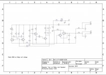
Deciphering the schematic wasn't easy—I have to admit, I still have difficulties to discern either of the attached pics...
1) immediate trip.
2 ) +/- 0.65V
I feel good.
Many many thanks, again!
Deciphering the schematic wasn't easy—I have to admit, I still have difficulties to discern either of the attached pics...
Attachments

The pictures I have seen of the completed board shows 5 volt relays. That would be consistent with a nominal 12 volt supply and a 9 transformer.
Are there any details anywhere detailing the recommended supply voltage range. I've looked but couldn't just see anything.
This has confused a few builders I guess. (Many posts are about this)
Maybe it would be useful (for us novices) to add a section to post #1 (voltage range, pros/cons of either(like shorter trigger time ), minimum required..., proper attachment, testing?)
otoh, what could we pester you with, if everything was perfectly documented?
- Home
- The diyAudio Store
- Speaker Turn On Delay and DC Protector Board Set (V3)