rsaumure: powering the SP board can be done in several ways from simple to more complex depending on what you believe the relays can handle over their expected lifetime and/or introducing noise into the signal to your speakers (read thru the forum to see if anyone had an opinion on this). So for two 12V relays you’ll need either 24VAC or 24VDC into the board. A number of opinions in the forum suggest a separate power source to the board if your transformer only has one set of 24VAC secondaries. If the transformer has two separate secondary sets (one being ~24VAC) you’re in (semi) good shape. As I have yet to buy a transformer that outputs exactly what it’s supposed to on it’s secondaries (load or no-load measurement; usually always higher) you’ll be driving the relay coils with more voltage than they really need (possibly shortening their lifespan). Since you can put 24VDC directly into the board (instead of VAC) the second variation includes putting in a voltage regulator board (either powered by your main tranny or a smaller secondary one) to guarantee a closely controlled 24VDC output ( which means another thing or two taking up space in your build). The approach I used was to drive the protection board using a Mean Well RS-15-24 switching power suppply. You can use the mains leads that drive your tranny and you have a regulated 24VDC supply to drive the protection board (but, again, something else taking up space but it’s really a small unit). Opinions forum folk?Cool - thanks I was measuring without any load on the secondaries. I am using the 12 V relays. Right now I am trying to figure out how to stuff everything into the 4U Deluxe chassis. Did nor realize how tight everything was going to be inasmuch as I built the Universal Power Supply all on one board. Need to go back and break off the diode sections. In practice when installing the speaker protection circuit I assume you just pull power directly from the toroidal transformer? Much thanks!
Regards, Pete
Thanks for your help. When I was testing this I believe I was able to get the board to function with 12v DC through a 7812BT ON Semiconductor Linear Voltage Regulator with a separate transformer. My plan was to use the separate transformer and regulator to power a capacitive touch switch and power relay. While the little transformer will be fine for the relay, I am hesitant to add much more to it. Started busting apart my Universal Power Supply to give me more flexibility with layout - there is only so much you can cram into this space. I have 2 sets of secondaries on the Antec 4218 so I could use that either directly or with another Semiconductor Linear Voltage Regulator as you suggested? I suppose I should not test the protection board using the transformer only - i.e. the rest of the power supply should be hooked up?
Personally I would use a AC/DC voltage regulator board based on the LM317 (adjustable output) chip to go in between the tranny Secondaries and the protection board. You can get small, complete circuits on EBay for dirt cheap (just have to wait for a shipping delay since they all come from China). Trust me it’s easier to buy a pre-built one than put one together yourself. Some folks would just have you just use the regulator chip itself (if you can find 7824 chips anymore and you would need 30VAC input) but a whole circuit is smoother and quieter. Unfortunately your Antec is 18+18 and you would need something like 27-28VAC to drive a LM317 circuit to get a steady 24VDC out (somebody can correct me on that). If you dropped the relays to the 5V ones you could use your 18+18 for a good 10VDC out of the regulator circuit.
I looked back on my build notes and they recommend 24VDC to drive the two 12v relays. But, I also bought a “Universal Speaker Protect PCB from the JLE store on EBay and he incorporates a 7812 into his circuit (using two 12V relays) and his board only requires 12-15VAC input to run so maybe your use of the 7812 will work fine. I would think you would need a heat sink on it though (since you’re pushing through 18VAC). Did you find the chip getting warm?
I looked back on my build notes and they recommend 24VDC to drive the two 12v relays. But, I also bought a “Universal Speaker Protect PCB from the JLE store on EBay and he incorporates a 7812 into his circuit (using two 12V relays) and his board only requires 12-15VAC input to run so maybe your use of the 7812 will work fine. I would think you would need a heat sink on it though (since you’re pushing through 18VAC). Did you find the chip getting warm?
Do you know where one can find a schematic for the Universal Speaker Protect PCB circuit?
Lester sends them when you buy the JLE boards I believe, along with the BOM and build guide.
I've got the diyAudio Store board but was wondering if two of those boards would be better for me to keep the output commons separate. I would really prefer to see what the design is before purchasing.
I looked back on my build notes and they recommend 24VDC to drive the two 12v relays. But, I also bought a “Universal Speaker Protect PCB from the JLE store on EBay and he incorporates a 7812 into his circuit (using two 12V relays) and his board only requires 12-15VAC input to run so maybe your use of the 7812 will work fine. I would think you would need a heat sink on it though (since you’re pushing through 18VAC). Did you find the chip getting warm?
I really did not have it connected long enough to see if the chip got warm but it seemed to work with 12 volts dc. I will try integrating the speaker protection board with my circuit to control the relay and see if it does get warm. Right now the regulator does not get warm at all and only the transformer is throwing off a little heat. Transformer is 12 vdc 2 VA. I could probably use something a little larger if I had to - Zettler goes to 2.8 VA.
YouAgain: both the DIYAudio board and the JLE boards work the same way, they separate out the L&R (+) lines out of the amp and control each through their own relay circuit. The L&R (-) amp leads can either be combined&grounded then sent to the speakers or held separately and sent to the speakers. Grounding the relay boards and the speakers’ (-) only is necessary if you’re getting hum. JLE does sell independent speaker protection relay boards if you really want to separate the L & R (+) leads (like for monoblock amp designs).
All the other components on both the boards are for DC protection circuitry so your speakers are protected in case of an amp circuit failure.
All the other components on both the boards are for DC protection circuitry so your speakers are protected in case of an amp circuit failure.
I really did not have it connected long enough to see if the chip got warm but it seemed to work with 12 volts dc. I will try integrating the speaker protection board with my circuit to control the relay and see if it does get warm. Right now the regulator does not get warm at all and only the transformer is throwing off a little heat. Transformer is 12 vdc 2 VA. I could probably use something a little larger if I had to - Zettler goes to 2.8 VA.
Other forums have mentioned that the 12V relays will work fine down to 9V for each. Go ahead and try it the way you have it now. If the channels start intermittently dropping out while you’re listening you may have to incorporate some capacitors to stabilize the 7812s output to the relays’ coils.
YouAgain: both the DIYAudio board and the JLE boards work the same way, they separate out the L&R (+) lines out of the amp and control each through their own relay circuit. The L&R (-) amp leads can either be combined&grounded then sent to the speakers or held separately and sent to the speakers. Grounding the relay boards and the speakers’ (-) only is necessary if you’re getting hum. JLE does sell independent speaker protection relay boards if you really want to separate the L & R (+) leads (like for monoblock amp designs).
All the other components on both the boards are for DC protection circuitry so your speakers are protected in case of an amp circuit failure.
Thanks turion64. I'm building mine as monoblocks in a single case and want the grounds to bond at a single chassis point only. These boards may be great for that and the price is right for the next amp project. I've built the diyAudio board and was planning to ground the board to the chassis and then ground each channel to the chassis through separate isolators using the diode bridge/10 Ohm resistor/ series capacitor circuit that is popular. I've tried it on the bench and the extra 10 Ohms in the sense circuit doesn't affect the trip point of the protection circuit at all. I have two pairs of speakers that I love and both have no replacement drivers available so I can't take the risk of DC on them in a failure. This was never a problem with tube amps and output transformers.
This was never a problem with tube amps and output transformers.
Have you gone to the Dark Side and left the world of Tube Amps...the Holy Grail of sound??? 😱
A tube build is on my bucket list...but from a kit.. I’m too lazy to do all the necessary calculations for an original build.
Cheers,
Pete
Have you gone to the Dark Side and left the world of Tube Amps...the Holy Grail of sound??? 😱
A tube build is on my bucket list...but from a kit.. I’m too lazy to do all the necessary calculations for an original build.
Cheers,
Pete
Pete, I haven't left the world of tube amps but I've certainly been dragging my feet about finishing my F6. It didn't help me that I had to pack up and move my things to storage for 6 months while I started a new job and moved house. I'm finally getting comfortable in my home work space but there are plenty of things that I still can't find yet.
Years ago I built a pair of dc coupled tube monoblocks and spared no expense on them. They have an interesting harmonic profile and they compress as you drive them harder and do that thing that some of the great recording studio tube limiters do. It's not reality but it's a show and a show that I love and it keeps me up late because I always want to put another record on. But after years of it I really want better bass control and more power before distortion so on to the F6. The funny thing about this is that after accumulating some medical bills and then a gap in employment, I decided to pull out the Black Gate WKZ high voltage electrolytic capacitors from these amps and another and sell them on eBay as the demand was crazy. The thousands of dollars that I got from that covered all of the expenses of my monoblocks and of another tube amp plus part of the cost of my F6. And my friends laughed at me for paying $140 each for the 100uF+100uF@500V WKZ. I enjoyed them for well over a decade and still made a huge profit on them.
The F6 has become a bit of a layout puzzle as I have two big transformers and a discrete rectifier board plus the soft start, speaker protector and it's shielded power supply. I still have to fit eight of the electrolytics on each side and the only way I'll pull that off is to stack them vertically.
Mike
Attachments
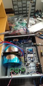
Pete, I haven't left the world of tube amps but I've certainly been dragging my feet about finishing my F6. The F6 has become a bit of a layout puzzle as I have two big transformers and a discrete rectifier board plus the soft start, speaker protector and it's shielded power supply. I still have to fit eight of the electrolytics on each side and the only way I'll pull that off is to stack them vertically.
Mike
Mike: thanks for the historical perspective on your amp building journey. I came into this DIY amp game late and Black Gates sort of have this legendary status which I never got to personally experience. I’ve found a few types in various (old) amps but I don’t think my old ones are as valuable as yours were. They certainly gave you some financial breathing room.
I’ve only started my amp building hobby and started with chip amps based around either LM3875 or LM3886. The LM3886 variation (My_Ref) of the late Mauro Penasa was exquisitely fleshed out by another Italian gentleman named Dario Fremen. They are not super powerful but the harmonics are beautiful and has a dedicated follower base who have made numerous tests on changing various components & recommendations that allow you to adjust the amp to your speakers strengths or weaknesses. It’s all lower voltages so one doesn’t have to worry about electrocution like with tube amps. So I also have missed all the solid state builds that have come before or parallel to the chip amp craze but have read about the series you are building now.
As far as your struggles with fitting everything into your F6 build, to paraphrase Roy Scheider...you may need a bigger boat...😉
Pete
Thanks Pete. I like the bigger boat analogy! I'll make this chassis work but I'm a little bit claustrophobic and looking at the project in it's present state triggers a little of that constrained space discomfort.
Tube amps are rewarding and working with the energized undersides of tube amps really isn't dangerous if you keep one hand in your pocket while putting a test probe on a point.
Sound Practices magazine from the '90s was what drew me into diy tube projects. It was a worldwide hit but the rise of the internet hurt it. I recommend finding the back issue set on CD-ROM and having a look. The view of that world wide pre-internet culture is fascinating. The articles are amusing and full of personality and you may find a project to build. My amps were built from schematics from SP articles.
Mike
Thanks ! I just a link to email Joe Robert's? about the Sound Practices issues 1-16 CD. Hopefully he'll get back to me
Regards,
Pete
Regards,
Pete
Parts source for Omron Relays
I have version 3.0 speaker protection board. Problem is I can't find the two Omron relays with the Version 3.0 board matching the relays. Part #653-G5LA-14-CF-DC12 is obsolete and can't find a source to purchase from. Mouser suggest another part but the relay legs are different and won't match the board solder holes. Thanks for any suggestions for a source to purchase from. Did catch the "C" part number EBC for the transistors so happy for that and swapped BC so did not ruin the transistors .
I have version 3.0 speaker protection board. Problem is I can't find the two Omron relays with the Version 3.0 board matching the relays. Part #653-G5LA-14-CF-DC12 is obsolete and can't find a source to purchase from. Mouser suggest another part but the relay legs are different and won't match the board solder holes. Thanks for any suggestions for a source to purchase from. Did catch the "C" part number EBC for the transistors so happy for that and swapped BC so did not ruin the transistors .
Thanks for the tip. Wonder what others are doing for these parts. Anyway ordered relays that had the same pin out and coil ohms and measurements to the holes in the board. From China so maybe by this fall will get parts?? Thanks again and stay safe.
I have version 3.0 speaker protection board. Problem is I can't find the two Omron relays with the Version 3.0 board matching the relays. Part #653-G5LA-14-CF-DC12 is obsolete and can't find a source to purchase from. Mouser suggest another part but the relay legs are different and won't match the board solder holes. Thanks for any suggestions for a source to purchase from. Did catch the "C" part number EBC for the transistors so happy for that and swapped BC so did not ruin the transistors .
Look to Mouser part # 653-G5LE-1-DC12
Cheers, Pete
- Home
- The diyAudio Store
- Speaker Turn On Delay and DC Protector Board Set (V3)