In my understanding the spark always generates a shockwave (as a bright spark does not occur in the absence of hot plasma), but the distance at which that shockwave dissipates and the doublet stabilizes increases as spark energy increases.
Does your microphone have the BW needed to see the doublet clearly? From what I can see that mic has distance across the transducer that is about the width of a 70us period.
Does your microphone have the BW needed to see the doublet clearly? From what I can see that mic has distance across the transducer that is about the width of a 70us period.
It might be a problem with the marx generator since it works by firing a sequence
of small sparks before firing the big one?
The MK102 is one inch capsule 20 kHz ( 0...-3 dB):
https://www.elektroakustika.cz/images/rft/mv/mv102/MK102.1_MK103.1_S1+2_ID[1].pdf
I should probably get a smaller capsule as reference.
of small sparks before firing the big one?
The MK102 is one inch capsule 20 kHz ( 0...-3 dB):
https://www.elektroakustika.cz/images/rft/mv/mv102/MK102.1_MK103.1_S1+2_ID[1].pdf
I should probably get a smaller capsule as reference.
I received an EM258 microphone capsule. This is a lot like the Panasonic WM-61A but with a lower noise floor and probably somewhat worse frequency response.
When I measure the EM258 and EM172 response at the same time with a speaker, normalize to the EM258 response and then apply the EM172 calibration to the result, the resulting response is very flat up to 20KHz where the EM258 response begins to fail as a reference. I had been worried that my spark calibration was giving too much of a peak at 7KHz but comparing with the EM258 does not show any issues with the spark calibration. So I think I am on the right track.
Here is a ground plane impulse response derived from a spark doublet.
Attachments

I would like to duplicate as best possible your measurement process. More details on the software and process is what I need most.
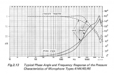
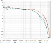
There are several valid questions from the plot. The higher end response doesn't look like what I have seen. The Phase plot should show a resonance near the top of the response curve and then a sharp rolloff in the frequency band.
The plot below is typical except for a 1" microphone. 1/2" and 1/4" will move everything up. Non-metal diaphragms will also have different resonances & tensions. However a lot of this is the physical construction physics.
Typically the capsules are pretty affordable and I'll try to source one or two and compare with my references.
Attachments
That is very relevant, because I was actually struggling with that part of the response.
1: Lifting up the capsule a few mm from the ground plane causes a very gradual tilt downward in the treble, 1db or so but it changes the look of the chart quite a lot.
2: The bump near rolloff is present but seems to respond heavily to SPL. At higher SPL the bump disappears and becomes more like the gradual rolloff in the chart I posted. Electronic overload seems to be a likely explanation since most of the SPL is at the corner frequency in the acoustic doublet where the observed compression is seen.
Both these effects are seen in the chart in my last post. Attached is a chart with the previous response on top and several other runs below. The response bump gets bigger when I reduce the gap length and/or reduce SPL. I suspect it may interact with interference.
Attachments
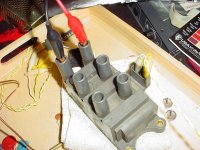
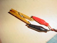
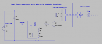
Here is a schematic showing what my spark generator looks like right now. Before I added the relay the most reliable method of not getting spark trains was to manually close the contacts which were two thumbtacks in the tail of a clothespin. The relay makes more consistent sparks with much less frequent spark trains due to switch bounce. Perhaps a reed relay would be best suited for eliminating switch bounce. I wonder if a reed relay could be triggered by the heapdhone output on my computer? Clearly I am stuck in the stone age with this, I'm hesitant to connect the computer to an ignition coil.
It repeats about every 70ms, so I can collect a large number of sparks and average them to reduce noise.
Also pictures of the ground plane setup.
It repeats about every 70ms, so I can collect a large number of sparks and average them to reduce noise.
Also pictures of the ground plane setup.
Attachments


Hi! This is a very interesting endeavour as it seeks as I understand it a universal reference towards which mic can be calibrated. Now, it is still quite advanced and I wonder if when ready, it would be possible to create a calibration device that anyone could build out of standard, cheap items. Of course one has to ease the requirement on accuracy a bit but say that we could aim for within a dB 20-20k?
I'am envisioning something like the Big Mac cost reference - universally available made out of well specified items 🙂
BOM (purely mechanical!):
- A box
- Pieces of metal (?) etc to form a "clap" (?) or spark?
- Mic interface
- Clap trigger
Recording using REW...
All the items should be made out of ordinary, easily sourced stuff that can be trusted to be the same the world around. Cost: < 25USD? 10?
The MicCalBox, MCB, should of course firstly be compared and calibrated with your spark thingy before release 🙂
Possible or still to many variables/uncertainties?
But maybe an optimized sparker is just this ;-D
//
Last edited:
The big problem is interference and seems to be the largest issue out of all of my testing. Also possibly acoustic overload.
On the software side, I use Linux and have a script I wrote that exploits sox in a really hacky way to detect sparks in a time aligned way and average them together. This is mainly for noise reduction purposes and doesn't necessarily give a better result. Some single spark recordings are better than 100 averaged together. The spark generation is an enormous wildcard.
On the software side, I use Linux and have a script I wrote that exploits sox in a really hacky way to detect sparks in a time aligned way and average them together. This is mainly for noise reduction purposes and doesn't necessarily give a better result. Some single spark recordings are better than 100 averaged together. The spark generation is an enormous wildcard.
Ok so spark is the ultimate reference once one can get it to work. My idea has perhaps some merit then in the sense that it would be a more repeatable way of calibrating mics out there. Now, I might be OT here as this is about.. sparking 🙂 But still, I couldn't help thinking about an application for it to make good for more people...
If I may, shortly... when thinking about materials and/or products to use for building a true world sound source reference, it is in fact not so easy to come up with a contraption that I, someone in Tokyo, Brisbane as well as in Antannarivo could build and be sure that if "clapped", it would create *the same* "sound" (whatever that would mean).
With what/how would you build it? Wood is different, IKEA changes its products, bricks differ,....
Fascinating really..
//
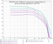
I tried a few different angles for the EM258. Information is in the legend of the attached chart.
The gradual rise below 5KHz seems to behave like some viscous relaxation or diffusion. It seems to correlate more with spark gap length than with SPL or distance. It is very puzzling.
Multi-recording averages have to be time aligned carefully, as any uncertainty in the timing manifests as multi-sample smoothing in the resulting impulse response and may artificially reduce the upper BW.
Attachments
Here is a chart at 2 gap sizes with 3 measurement distances for each gap. Measurements are intentionally overlayed for each gap size.
It can be see that the frequency balance does not change with distance, ruling out acoustic overload as a cause for the midrange rise. The frequency balance does change with gap size, with the larger gap producing more midrange content.
At the highest SPL, compression is apparent at the frequency range where SPL is highest in the acoustic doublet. It's not obvious exactly what is overloading.
Too many tests in the overload region actually causes the ECM itself to drop in sensitivity. I had to come back the next day for the sensitivity to return. I don't know why this may be. Stored charge on the Jfet gate? Temporary depolarization of the diaphragm?
There is no obvious sign of electrical interference as it normally precedes the acoustic wave.
Attachments

Wow - you found traces of hysteresis in the capsules? Have you tried to bootstrap the ECM for higher SPL capability? Post #135 Fixed gain field recorder?
//
//
The compression is equivalent to something like 25% THD. The SPL rating of the EM258 is 115db. If the SPL max is determined at 1% THD, then 25% compression is far more than expected.
The peak voltage for the doublet was 142mV. IIRC a BJT LTP compresses to 50% at 47mV. So slew rate seems like a possible explanation. 1db compression occurs at about 18mV, so it seems like it would be ideal to keep the mic output voltage under 10mV or -38dbu for preamps without sufficient BW.
However my input works fine up to 96KHz at full input, so this doesn't seem to be the explanation.
So far tests seem to indicate that
1: The rise in the midrange is acoustic in origin, possibly from the ground plane or spark.
2: The microphone compresses by 25% at 142mV peak output voltage in response to a doublet, which corresponds to a peak SPL of 106db. The datasheet gives max SPL as 115db (corresponding to 117db peak). It seems excessive considering the max SPL is still 10db away and my computer preamp gives the capsule 2.68V to work with.
Last edited:
I now realise that your capsule only has 2 terminals and hence, the bootstrapping cant be done as I understand it. For it to work, the fet pins need to be accessible i.e. 3 pins accessible.
//
//
Increasing the max SPL is unlikely to be any use because louder spark tests do not resemble the datasheet curves and known response for the microphones I have tested.
The rise in the midrange depends very heavily on spark gap and little else. The ideal for this spark generator seems to be between 0.5mm and 0.2mm. Too high or too low and the anomaly increases.
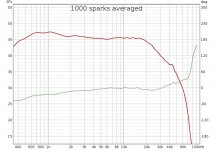
Here is the chart from 1000 sparks averaged together. This was taken with my window AC running.
I also ruled out the 3-ply wooden ground plane attenuating HF by replacing it with an acrylic sheet. It seemed to make very little difference.
So the only thing that really significantly affects the midrange rise is spark gap length.
The rise in the midrange depends very heavily on spark gap and little else. The ideal for this spark generator seems to be between 0.5mm and 0.2mm. Too high or too low and the anomaly increases.
Here is the chart from 1000 sparks averaged together. This was taken with my window AC running.
I also ruled out the 3-ply wooden ground plane attenuating HF by replacing it with an acrylic sheet. It seemed to make very little difference.
So the only thing that really significantly affects the midrange rise is spark gap length.
Attachments
I have used thunder claps not to calibrate frequency response, but to match mics. FR depends a lot on the distance of the thunder, closer has more HF of course. But sound the source is large, broadband and far enough from the mics that I'm confident both mics get exactly to same sound.
I am approaching a theory on what is causing the midrange issue.
I made an LTspice schematic to generate perfect doublets as .wav files. When I integrate this waveform inside LTspice, there is a step in the output that resembles the anomaly in the recorded sparks. When I load the generated doublet into REW, the issue shows up.
So it seems there is an inherent inaccuracy to the sampling of doublets. The recorded doublet is 42uS long, only 8 samples at 192KHz. Any inaccuracy in sampling the positive and negative halves of the doublet may result in extra LF content as the halves should cancel completely in a true doublet.
The spark gap length may affect this by changing the length or shape of the doublet.
It only makes sense that needing significant dynamic range from a recording of just 8 samples may incur some penalties to accuracy. It may vary widely between ADCs as well.
This is only a theory based on what happens in LTspice. But Scott Wurcer was able to do it seemingly without having any of these issues.
How many bits of resolution is needed to get useful information? Maybe a DSO would be able to catch enough data at a high enough sample rate?
If you take the response curve and do a reverse FFT does the resulting impulse make sense?
At this stage while I'll continue to play with this I'll stick with the Pioneer ribbon for calibration.
If you take the response curve and do a reverse FFT does the resulting impulse make sense?
At this stage while I'll continue to play with this I'll stick with the Pioneer ribbon for calibration.
- Home
- Design & Build
- Equipment & Tools
- Spark calibration of microphones