Ok will practice some more. Last time I did it I hung a small screwdriver with a alligator clip and wire attached to the hole on the transistor. Still never fell off. Which transistors should I remove; Q3-Q6? Also even with my widest solder tip I couldn’t heat all 3 at one time. So I instead moved the tip back and forth among all 3 pins.
Also at this point since I broke Q2 I assume I have to buy a set of transistors anyways so if I break another it’s not a big deal.
Also at this point since I broke Q2 I assume I have to buy a set of transistors anyways so if I break another it’s not a big deal.
Last edited:
Lay the iron's tip down across the connections. The barrel of the iron will be roughly parallel to the board.
I know I won't do videos here but I have nothing else. This is an old video but shows how you bridge all 3 connections at once. I know it's a different style of board but the idea is the same to heat all legs.
https://www.bcae1.com/temp/removingpartsfromolderorionamplifiers01.avi
I know I won't do videos here but I have nothing else. This is an old video but shows how you bridge all 3 connections at once. I know it's a different style of board but the idea is the same to heat all legs.
https://www.bcae1.com/temp/removingpartsfromolderorionamplifiers01.avi
After the second transistor I started getting the hang of it and pulling them out in less than 5secs of heat. Unfortunately I couldn’t do the hang them off with gravity trick because I couldn’t straighten out the legs without feeling like they were going to snap. So instead I flipped the board and pulled up softly with electronics tweezers once the solder bridge was molten. Easy peezy! Thanks Perry.
Now onto the unfortunate results. None of the transistors are shorted on any legs and the circuit board is no longer shorted either with the transistors out. The twilight zone mystery continues…
Now onto the unfortunate results. None of the transistors are shorted on any legs and the circuit board is no longer shorted either with the transistors out. The twilight zone mystery continues…
Use wires (easier to solder/desolder) to connect each transistor back to the board, one at a time. You may need to install it on a temporary heatsink (below) because, alone, it will heat quickly. Do this with each of the transistors (one at a time). Does one of the transistors cause the short to return?
Do you have any relatively low value resistors (4.7-10 ohms)?
Don't worry about breaking the legs. These transistors will not go back into the amp to stay. We're just using them for troubleshooting.
Do you have any relatively low value resistors (4.7-10 ohms)?
Don't worry about breaking the legs. These transistors will not go back into the amp to stay. We're just using them for troubleshooting.
Attachments
By one at a time do you mean only have one connected at a time or just keep adding one additional one?
Yes I do have a few resistors low ohm resistors on hand.
Yes I do have a few resistors low ohm resistors on hand.
For that bank of outputs, only one transistor installed at a time. That may change later.
If you can't get DC with one at a time, I'd want you to install the remaining good ones but instead of connecting the base directly to the board, you'd insert a resistor. That way, if the short returns, you should be able to determine where it originates... hopefully.
If you can't get DC with one at a time, I'd want you to install the remaining good ones but instead of connecting the base directly to the board, you'd insert a resistor. That way, if the short returns, you should be able to determine where it originates... hopefully.
So I have the instructions clear. Wire one transistor at a time with wire and check for DC.
I already tried something similar. I just inserted it very snug and checked for continuity between all legs and the circuit to verify contact. Didn’t get any meaningful DC, shorts or heating up of any transistors after 30secs to 1min. I did notice that sometimes the DC would slowly increase but remain in the 8mv to 150mv range. If I disconnected the DMM and reconnected it, it would reset to about 8mv.
But will try with the soldered wire approach for better connectivity. Any load? Lamp? Any audio input?
I did the test one transistor at a time for a minute each time and no DC presented itself. Actually the DC was approx a constant 8mvdc. Also tested for shorts after each transistor and none occurred. I stopped the test at a minute because I don’t have any heatsinks to attach them to and the transistors being tested were getting close to 100F around the minute mark. The only other transistor I also noticed above room temp were Q43 and Q50 on the power supply which also were around 100F at the minute mark. All the others in the power supply and the output banks were room temp.
Last edited:
What do you think of breadboarding this test? I can place the amp pcb back on the heatsink for Q43 and Q50 and I can install wires from Q2-Q6 to the breadboard and play with different scenarios there? Also I found some nice TO-220 individual screw on heatsinks for each transistor being tested in the breadboard.
The breadboard is just another opportunity for intermittent connections.
Do you have the screw-on heatsinks on hand, at this time?
Do you have the screw-on heatsinks on hand, at this time?
ok thanks. I was thinking about buying those screw-on heatsinks with the breadboard. I guess the best option is to buy the screw-on heatsinks for only the output transistors being tested and install the amp PCB back on the heatsink to protect Q43, Q50 and anything else that might overheat. I would really like to test some audio now that DC is not present with one transistor. I'm going to try and find some really cheap or free used speakers. Maybe I'll swing by a Goodwill or something.
Last edited:
The light bulb will tell you what you need to know. A 40w in series with the speakers will help to protect the speaker while allowing audio to pass.
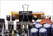
Don't you have a ready source for the 3/8"x1" aluminum bar stock that I showed? Binder clips are definitely readily available. The Kapton isn't required for a single transistor. Just keep it insulated from anything else that's conductive.
Don't you have a ready source for the 3/8"x1" aluminum bar stock that I showed? Binder clips are definitely readily available. The Kapton isn't required for a single transistor. Just keep it insulated from anything else that's conductive.
I unfortunately dont have any aluminum bar that can be used as a heatsink. Will have to buy one. Thanks for the lightbulb idea, unfortunately dont have any on hand either. I think finding a cheap or free speaker will be more economical than a socket and bulbs. Also I really don’t want to take any chance with my speakers as they cant be easily or cheaply found.
Don't you have a desk lamp that you could use?
If there is any sort of metal production/sales/welding shop near you, they will probably give you a piece of cut-off aluminum suitable. If not, you can clip the transistors to any metal with a flat surface.
If there is any sort of metal production/sales/welding shop near you, they will probably give you a piece of cut-off aluminum suitable. If not, you can clip the transistors to any metal with a flat surface.
I found an aluminum level that I could use as a heatsink. It’s painted but I hope that doesn’t reduce the heat transfer too much. I do have a desk lamp but would need a light bulb. Would a common 60w work in case I can’t find a 40w? In series there is no risk to my speakers with the lamp?
No risk? If you're using a speaker that can only handle a couple of watts? What's the rating on the speaker?
60w is OK. Certainly better than nothing. Remember, you don't have to use the speaker at all. The lamp will tell you when it has DC. You can touch it across the 35v rail voltage to see what it will look like when you get 35v on the speaker output.
None of this absolutely reduces risk 100%. You have to be attentive and use common sense.
Use a dot of heatsink compound on the back of the transistor before you clamp it. Remember not to let the level touch anything if you don't have an insulator behind the transistor.
Unfortunately don’t have any incandescent bulbs. Closest thing is halogen. If I connect a speaker and/or bulb can I in parallel connect my DMM to check for DC? How long should I leave the amp powered waiting for dc? To test the light bulb on the rail where to I connect for ground? Speaker negative, chassis ground or the ground terminal for power?
"How long should I leave the amp powered waiting for dc?"
^^ how long did it take to appear before?
Connect the lamp across one of the rail caps if the amp is out of the sink.
Halogen is incandescent but likely high-power so possibly not useful here.
Does the lamp light across the rail cap? It won't get bright. It will only slightly light up, if at all.
^^ how long did it take to appear before?
Connect the lamp across one of the rail caps if the amp is out of the sink.
Halogen is incandescent but likely high-power so possibly not useful here.
Does the lamp light across the rail cap? It won't get bright. It will only slightly light up, if at all.
- Home
- General Interest
- Car Audio
- Soundstream Rubicon 502 with DC voltage in right channel