both - what ?
P3 and P4 ?
or you already altered values of R34 and R35 ?

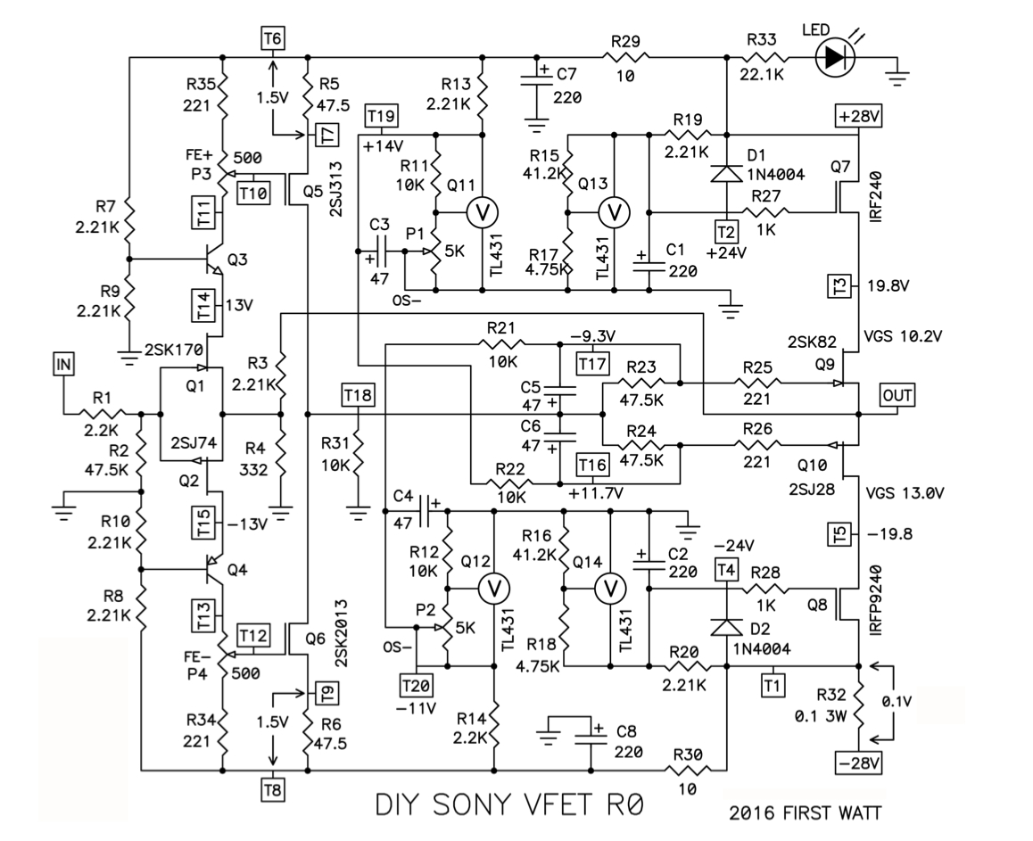
check for P3 : upper leg of R35 and T10 , ohmmeter must read 0
check for P4 : upper leg of R35 and T12 , ohmmeter must read 0
I followed these instructions and they did read 0.
Now I have to order some replacement resistors for R34 and R35.
Getting parts in and replacing them may take a while because of my busy family life.
Regards,
Dan
Hey Dan,
The exact value is not important. If you don't want to wait, use in parallel
or in series parts you may already have. (Say, two 1k in parallel to get 500 ohms
or two 221R (the standard aleph gate resistor) in series).
Cheers,
Dennis
The exact value is not important. If you don't want to wait, use in parallel
or in series parts you may already have. (Say, two 1k in parallel to get 500 ohms
or two 221R (the standard aleph gate resistor) in series).
Cheers,
Dennis
Dennis,
You’re absolutely right. I’m a little OCD though so I’ll order the parts so it looks nice and neat.
Regards,
Dan
You’re absolutely right. I’m a little OCD though so I’ll order the parts so it looks nice and neat.
Regards,
Dan
The latest. I installed 392 ohms for R34 and R35. I measured 3.2V across both R34 and R35. I get around 1V at T6-T7 and the same across T8-T9. With a little tuning of these voltages I get 0V from T18 to ground. Everything seems to function as it's supposed to with the exception that the voltages across the two test points are still too low? Can't get too much over 1V.
Regards,
Dan
Regards,
Dan
The voltages are a beautifully match 1.13V across T6-T7 and T8-T9 with OV from T18 to ground.
Regards,
Dan
Regards,
Dan
Now I'm experiencing (thankfully) what other people have getting T18 to ground stable. What a PITA. So sensitive and a tendency to drift!
Regards,
Dan
Regards,
Dan
Looks like a one hour warmup is strongly recommended. After that things are perfect.
Regards,
Dan
Regards,
Dan
Been out of the loop for a bit on these vfets. Wasn't there talks that one more kit would be available sometime this year?
yup
be patient
cool thanks. Patience is one of my virtues so i'm not worried about it. I got so many other projects going on that I just wanted to make sure I didn't get too caught up that I missed it.
I have a reoccurring nightmare where I check the forum for new posts and the latest post says "all the new SIT kits are gone"
Adjust P1 for T16 equals the Vgs of 2SJ28 + 1V ( example: 68 wants +7.8V)
Adjust P2 for T17 equals the Vgs of 2SK82 – 1V (example: 92 wants -10.2V)
Shouldn't the second line here be -8.2?
Regards,
Dan
take absolute value of bias voltage , added 1V on that ....... and it'll be clearer
look at schm and think ........
look at schm and think ........
Zen Mod take absolute value of bias voltage , added 1V on that ....... and it'll be clearer
look at schm and think ........
Think? Although fun and interesting. This particular project has maxed out all my ‘available resources’! 😉
Regards,
Dan
look at schm and think ........
Think? Although fun and interesting. This particular project has maxed out all my ‘available resources’! 😉
Regards,
Dan
Finally got to the bias stage. unfortunately I encountered problem on biasing the Vfets.
On one board, I can't lower the voltage under 20V (need to be 11V) with P1 at full turn. And on the other board the same, only on P2.
The frontend baising looks to go fine!
Need some guidance here please.
On one board, I can't lower the voltage under 20V (need to be 11V) with P1 at full turn. And on the other board the same, only on P2.
The frontend baising looks to go fine!
Need some guidance here please.
dantwomey, V-Fets are normally open devices, which means they will conduct current from drain to source even without a voltage present at the gate. This is why the bias supply is so important, the V-Fets have to be turned off or "throttled" before the supply at T3/T5 is present, otherwise they'll burn up.
For the first startup we want the V-Fets turned off (or throttled) more than necessary, just to be safe. The 2sk82 needs a negative bias voltage, so we initially make it more negative than necessary. The 2sj28 needs a positive bias voltage, so we initially make it more positive.
For the first startup we want the V-Fets turned off (or throttled) more than necessary, just to be safe. The 2sk82 needs a negative bias voltage, so we initially make it more negative than necessary. The 2sj28 needs a positive bias voltage, so we initially make it more positive.
Thank for your reply Zen Mod.
Yes Tl431 proper oriented, R11/12 - 10K, R13/14 - 2.21K
it must be something
replace TL431 in critical places
- Home
- Amplifiers
- Pass Labs
- Sony vFET Illustrated build guide