20mv on the output is almost perfect, at least in my world. I am glad Rich had someone to help him on his build. This amplifier is my favorite PP FW clone. I would check everything after more hours on the amplifier in a week or two. If everything is close to specs I would not touch a thing but my experience is that there will be some changes in bias and DC offset after break in.
So approximately after 25 hours of music playback, I checked the DC offset at the outputs, and measured:
Left: 43.9 mV DC
Right: 6.2 mV DC
Chuck (Botte) recommended that I make a minor adjustment on P1 with the amp warm, so I managed to get the DC offset the left channel output down to 4.3 mV and kept the voltage drop across R32 to 97mV. The right channel output still has a 6.2 mV DC offset.
This amp is fantastic with a very musical presentation. It plays everything well including classic rock, jazz and large orchestral music.
I have some questions about adjusting the output now that I have the VFET's installed. At turn on I have 24mv at the output and 32mv across R32. I'm I looking for 100mv across R32 and as near to 0 mv at the output as I can get?
Yes. This where you work with P1 and P2 to adjust the voltage drop across R32 to be just under 100 mV while keeping an eye on the DC offset on each output (within +/- 50 mV). Chuck used an 8 ohm dummy load across each output too. Just as you made incremental changes with P3 and P4 in setting the bias and offset of the front end, you should do similarly with P1 and P2 adjustments at this stage. Nelson Pass’ documentation explains this clearly.
You’ll also want to re-check T6-T7, T8-T9, and GND-T18 as you go along as settings drift as the amp warms up.
You’ll also want to re-check T6-T7, T8-T9, and GND-T18 as you go along as settings drift as the amp warms up.
Last edited:
Thanks rhing, I thought that was what Nelson was saying but I wanted to ask first before I did something wrong.
Yes. This where you work with P1 and P2 to adjust the voltage drop across R32 to be just under 100 mV while keeping an eye on the DC offset on each output (within +/- 50 mV). Chuck used an 8 ohm dummy load across each output too. Just as you made incremental changes with P3 and P4 in setting the bias and offset of the front end, you should do similarly with P1 and P2 adjustments at this stage. Nelson Pass’ documentation explains this clearly.
You’ll also want to re-check T6-T7, T8-T9, and GND-T18 as you go along as settings drift as the amp warms up.
Small increments and patience till you get the hang of it. Once you do it becomes easy. In my opinion 3 meters are necessary on each channel while doing this. Of course you can do one channel at a time.
Been working on the left channel adjustments today and have the following
T6-T7=1.546v
T8-T9=1.521v
T18-G= -162mv
R32-T1=91mv
DC out= -20mv
Is this close enough?
T6-T7=1.546v
T8-T9=1.521v
T18-G= -162mv
R32-T1=91mv
DC out= -20mv
Is this close enough?
I made fine adjustments on P1 and P2 to bring R31 voltage drop to between 95 and 99mV, but where you are looks good before allowing the amp to run a day or two. Some more experienced Pass DIYers my say otherwise.
You will be pleased once you have everything up and running. I love this amp in my system. I’ve played everything from early period polyphony from Anonymous 4 to large orchestral music to loud classic rock like The Who’s “Live at Leeds.” The soundstage is incredibly large in all three dimensions, especially depth-wise. The tone and timbral detail is pure and natural. This amp just grooves. It won’t make bad recordings sound like good recordings, but it will make them more enjoyable as it conveys more detail and greater presence.
This is definitely one of the best amps I’ve had in my system — maybe the best — and that includes my restored and modified Dynakit Stereo 35 and restored McIntosh MC240 P-P tube amps. I look forward to Mr. Pass’ next VFET amp project. Hopefully, it will be released in the next few months.🙂
I got the right channel dialed in and have been listening to the amp for over a week now and I’m very impressed with the sound. Very good with the Altec 19’s. Anyone know what the output would be for 16 ohms?
I would think the Altec Model 19’s are ideal speakers to pair with the Sony VFET amp. I wired my amp with Duelund DCA16GA for the amp to speaker binding posts hook-up wire, and Duelund DCA20GA for the RCA inputs to amp inputs hook-up wire. I also used the Duelund DCA16GA wire as speaker wire to my KEF LS50’s. Give the Duelund wire a try with your VFET amp and Model 19’s.
I used kimber TCSS inside of mine sounds good. I’ve seen Duelund resistors around but where do you get Duelund wire? Should I assume 7.5 watts output at 16 ohms?
Parts Connexion in Canada carries the Duelund cotton-insulated Tinned Copper hook up wire line. I used the 15ga Kimber TCX Teflon-insulated Copper wire for my power supply wiring. “The Lamb Lies Down on Broadway” by Genesis has never sounded better.
Not sure what the Sony VFET amp power output is at 16 ohms—definitely less than 15 watts per channel. Have you rechecked your bias settings and DC offsets yet?
Not sure what the Sony VFET amp power output is at 16 ohms—definitely less than 15 watts per channel. Have you rechecked your bias settings and DC offsets yet?
Hello,
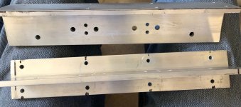
I am looking for 1 (or ideally 2, for a friend) set of brackets to run my Vfet kit.
They are out of stock on modushop.
Do you have one set to sell me ? Thanks 🙂
I am looking for 1 (or ideally 2, for a friend) set of brackets to run my Vfet kit.
They are out of stock on modushop.
Do you have one set to sell me ? Thanks 🙂
Hello,
I am looking for 1 (or ideally 2, for a friend) set of brackets to run my Vfet kit.
They are out of stock on modushop.
Do you have one set to sell me ? Thanks 🙂
Make your own. I bought 6 feet from Online Metals 2" x 2" Tee 1/4" thick.
Laid-out the boards to mark holes, etc. In the process of cleaning it up, will then blacken it using Jax's Chemical's Aluminum Blackener.
and mount it.
Rush
Attachments
Dear fellows, I’m in the process of completing my amp, but I encountered some problems with one board.
First I’d like to say that I made a mistake, and soldered Q5,6 wrongly on one board two Q5, and on the other two Q6
Now I get on one board -31V between G-T18, and -27V between G-17.
Can someone guide me were to look for a damaged device?
Thanks in advance.
First I’d like to say that I made a mistake, and soldered Q5,6 wrongly on one board two Q5, and on the other two Q6
Now I get on one board -31V between G-T18, and -27V between G-17.
Can someone guide me were to look for a damaged device?
Thanks in advance.
I'll postpone the thanks until completed but so far but build is going flawlessly up until part II where I'm powering up the front end. A very minor issue has risen which may have no impact whatsoever. All my measurements are perfect with the one exception. The DIY Universal power supply output is a little high at 31VDC. Should this be of any concern?
Regards,
Dan
Regards,
Dan
one thing is unloaded (AC x 1.41 roughly)
other thing is when loaded (AC x 1.25 roughly)
speaking of class A amp as load for PSU
other thing is when loaded (AC x 1.25 roughly)
speaking of class A amp as load for PSU
Another small bump in the road? All the voltages check out in part II except for four. C-T19 and G-T20 are double the guideline of 12v and G-T17 and G-T16 are double the suggested 10V.
Suggestions?
Regards,
Dan
Suggestions?
Regards,
Dan
you certain of good orientation of Q11 and Q12?
if yes , fiddling with P1 and P2 must get you in ballpark , regarding T19 and T20 voltages
that will sort T16 and T17 also
if yes , fiddling with P1 and P2 must get you in ballpark , regarding T19 and T20 voltages
that will sort T16 and T17 also
- Home
- Amplifiers
- Pass Labs
- Sony vFET Illustrated build guide