I think the main thing is to make sure P1 and P2 are adjusted so the voltages at
T16 and T17 are sufficiently high so the vfets don't conduct much current.
Since you don't have the original voltages measurements, I would just maximize
the T16 and T17 voltages. You may spend a bit more time adjustment, but
aside from that, I don't anticipate any difficulties.
Hopefully other members can chime in.
Cheers,
Dennis
Thanks Dennis for the reply. If I knew what the range was for the VFETs I could eliminate some of the adjustment by setting p1 and p2 to the top of the range.
My sets were within 0.1vgs left to right so just set the pots up to match the other side and be quick to make sure you don't exceed to much over 100mv on the 0.1ohm power resistor during turn on. If you do get over 100mv just back P1 and P2 off a little and try again.
Last edited:
Thanks Dennis for the reply. If I knew what the range was for the VFETs I could eliminate some of the adjustment by setting p1 and p2 to the top of the range.
Hi,
do you have the single turn pots or multi-turn?
If single turn, did you have a struggle to get
them to adjust to the right voltage? They are
super twitchy! Once I got close to the right
voltage, I found that just tapping the pcb
would bounce the voltage around! 😱
So, I put the project on hold, two months ago.
This after the thing sitting on a shelf
since April of 2017. 🙁
Stones, Idon't think mine were that close but thanks for the info about the 0.1 ohm resistor stones.
Ichiban, I have the single turns and found them hard to get right until I put in the 2013/313 transistors and changed the resistors back to originals.
Ichiban, I have the single turns and found them hard to get right until I put in the 2013/313 transistors and changed the resistors back to originals.
Ichiban, I have the single turns and found them hard to get right until I put in the 2013/313 transistors and changed the resistors back to originals.
I have the 2013/313 Toshibas installed. What original resistors ?
The kit I received had fqp3n30/3qp3p20 mosfets for Q5/Q6. It was later discovered that with those parts you needed to change P3/P4 to 1K and R34/R35 to 500 ohm to get the mosfets to the 4 volts needed to turn them on. From Post 334 of this thread.
The kit I received had fqp3n30/3qp3p20 mosfets for Q5/Q6. It was later discovered that with those parts you needed to change P3/P4 to 1K and R34/R35 to 500 ohm to get the mosfets to the 4 volts needed to turn them on. From Post 334 of this thread.
Thanks.
With tremendous help from Chuck (Botte here on diyAudio.com) on the Sony VFET bias settings, I have completed my build and I am very impressed with this amp with only 6-7 hours of music playback.

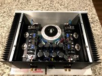
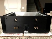
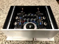
As I previously mentioned, I purchased a set of untested (unmatched) Sony VFETs from wdecho that he bought from Acronman a while back. He also included a pair of the T-brackets, mica insulators and a pair of the PCBs. After budgeting my money and purchasing all the parts through Mouser, Parts Connexion, the diyAudio store and the local Ace Hardware, I set off on measuring and matching resistors and capacitors and followed 6L6's excellent build guide and Nelson Pass' instructions.
Chuck really helped me with biasing the Sony VFETs and then we set it up in his system to audition the amp. The DC offset was kept well close to 200mV on each channel with the final settings. Having a great local resource like him in the Twin Cities is a real blessing. It sounded like a freshly built amplifier on his very efficient horn speakers. We then tested it with his distortion analyzer to see how closely matched each channel was since the VFETs were no tested and matched by Nelson Pass.
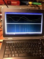
The photo shows the spectral analysis for the right channel. To my pleasant surprise, the left channel was virtually identical to the right channel. THD on the right channel measured 0.0130% @ 1 watt, while THD on the left channel measured 0.0135% @ 1 watt. It was time to close up the chassis and take it back home to enjoy.
I plugged the amp into my system consisting of an Audio Research vacuum tube phono stage, an Audio Research vacuum tube line stage and a pair of KEF LS50 monitors.
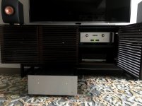
This amp has no problems driving the KEF's with the gain from my ARC LS7 line stage preamp. Chuck advised me to give this amp a lot of hours for it to really settle in, but I have to say that I am already impressed. The sound is so natural and clear. This is my first Pass DIY (and solid state amp) project ever, and just following Nelson Pass' documentation, 6L6's build guide and sage wisdom from wdecho and botte really made this project a success. Thanks again all for the help.


As I previously mentioned, I purchased a set of untested (unmatched) Sony VFETs from wdecho that he bought from Acronman a while back. He also included a pair of the T-brackets, mica insulators and a pair of the PCBs. After budgeting my money and purchasing all the parts through Mouser, Parts Connexion, the diyAudio store and the local Ace Hardware, I set off on measuring and matching resistors and capacitors and followed 6L6's excellent build guide and Nelson Pass' instructions.
Chuck really helped me with biasing the Sony VFETs and then we set it up in his system to audition the amp. The DC offset was kept well close to 200mV on each channel with the final settings. Having a great local resource like him in the Twin Cities is a real blessing. It sounded like a freshly built amplifier on his very efficient horn speakers. We then tested it with his distortion analyzer to see how closely matched each channel was since the VFETs were no tested and matched by Nelson Pass.

The photo shows the spectral analysis for the right channel. To my pleasant surprise, the left channel was virtually identical to the right channel. THD on the right channel measured 0.0130% @ 1 watt, while THD on the left channel measured 0.0135% @ 1 watt. It was time to close up the chassis and take it back home to enjoy.
I plugged the amp into my system consisting of an Audio Research vacuum tube phono stage, an Audio Research vacuum tube line stage and a pair of KEF LS50 monitors.

This amp has no problems driving the KEF's with the gain from my ARC LS7 line stage preamp. Chuck advised me to give this amp a lot of hours for it to really settle in, but I have to say that I am already impressed. The sound is so natural and clear. This is my first Pass DIY (and solid state amp) project ever, and just following Nelson Pass' documentation, 6L6's build guide and sage wisdom from wdecho and botte really made this project a success. Thanks again all for the help.
Last edited:
Congratulations Rich. With some more tedious work on the DC offset you should get it lower than 200mvs. The norm recommendation is 50mvs but under 100mvs should be fine. Let it break in for a week or two and settle in some then then recheck the bias and try and lower the DC offset some more. With more practice you should be able to get the dc offset around 50mvs. DC on the output moves the drivers in you speakers before the music starts playing limiting the travel somewhat. I use and like single turn pots which are touchy but with practice can be adequately done. After some break in and hours on it I think you will find the bias has changed some along with the DC offset. Unless I am mistaken, have been many times, FW and Passlabs runs the amplifiers 24 hours then sets the bias again on all his products.
Last edited:
Thank you again for selling me the Sony VFETs. I am grateful you persuaded me to pursue this project, and now I am enjoying this amp. I will open up the chassis and fine tune the bias and DC offset after the amp has more play time. Those single turn pots really are touchy, but getting this far has developed a level of patience I didn’t know I had in me.
I am also going to implement Nelson Pass’s diode and resistor ground isolation circuit. There is the faintest buzz coming through, and Chuck determines it wasn’t coming from the transformer or interference from it.
Now I have to resist the urge to build another amp, especially with an upcoming single-ended Sony VFET amp kit. I knew this was a slippery slope. 🙂
Now I have to resist the urge to build another amp, especially with an upcoming single-ended Sony VFET amp kit. I knew this was a slippery slope. 🙂
Congratulations on your amp!
BTW, resistance is futile. 🙂
look like CardasRich
May I ask, which speaker terminals you used?
Rich
Well done. Really neat work.
May I ask, which speaker terminals you used?
Thank you. The speaker binding posts are Vampire BP-1HEX types that I purchased from Michael Percy Audio. I also installed Vampire CM1F RCA connectors in the Neutrik RCA-in-XLR connector housings for the inputs. The input wire is Duelund DCA20GA 20ga Cotton-insulated Tinned Copper, while the output wire is Duelund DCA16GA 16ga Cotton-insulated Tinned Copper. I used Kimber Kable TCX 15AWG Teflon-insulated Copper wire for the power-supply-to-amp connections, and Cardas quad-eutectic solder throughout.
This was my famiy’s Christmas gift to me, and all I had to do was supply the labor. My colleague and friend from work offered to drill out the countersunk holes for mounting the LEDs and faceplate to harmonize the First Watt aesthetic of the 4U Deluxe Chassis with my Audio Research gear.
My compliments to Nelson Pass for an excellent amplifier design and documentation to share the Sony VFET goodness with us DIYers.
Congratulations Rich. With some more tedious work on the DC offset you should get it lower than 200mvs. The norm recommendation is 50mvs but under 100mvs should be fine. Let it break in for a week or two and settle in some then then recheck the bias and try and lower the DC offset some more. With more practice you should be able to get the dc offset around 50mvs. DC on the output moves the drivers in you speakers before the music starts playing limiting the travel somewhat. I use and like single turn pots which are touchy but with practice can be adequately done. After some break in and hours on it I think you will find the bias has changed some along with the DC offset. Unless I am mistaken, have been many times, FW and Passlabs runs the amplifiers 24 hours then sets the bias again on all his products.
The 200mv was at t18. Output was about 20mv.
😀
The 200mv was at t18. Output was about 20mv.
😀
20mv on the output is almost perfect, at least in my world. I am glad Rich had someone to help him on his build. This amplifier is my favorite PP FW clone. I would check everything after more hours on the amplifier in a week or two. If everything is close to specs I would not touch a thing but my experience is that there will be some changes in bias and DC offset after break in.
The 200mv was at t18. Output was about 20mv.
😀
Thanks for clarifying. I should have written this in my notebook. I guess I was excited watching this amp come to completion.
Pass DIY Addict
Joined 2000
Paid Member
- Home
- Amplifiers
- Pass Labs
- Sony vFET Illustrated build guide