Hm, maybe I was a bit too optimistic in identifying the cause. 2mV is definitely not what you'd expect from this circuit, with all the filtering in the PSU and the on-board cap multiplier. Do you have access to a scope? How did you measure the 2mV? I suppose the hum/noise is audible? Would you say it's 50Hz or 100Hz? What happens if you short the inputs?
2mv is of course imprecise since it is based on a multimeter. Was too lazy to unpack the scope then. My "scientific" method is to connect a cheap 4 inch drive unit and put it close to my ear. It is not very audible at arm's length. Shorting the inputs does not make much difference. AC ground lifting also does not really work.
Papa is always having them centered around 8mA , though - you can go with practically anything between 6 and 10
I am finally getting around to building the Sony VFET P-P amp. I carefully measured and matched the resistors and capacitors, and I populated the boards following the schematic. One deviation from the schematic is the use of Bourns 1 kohm pots for P3 and P4 (PN 652-3386P-1-102LF) and Bourns 5 kohm pots for P1 and P2 (PN 652-3386P-1-502). This should allow me to properly set the bias high enough for FQP MOSFETs instead of the 2SK and 2SJ MOSFETS.
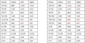
Going through the initial resistance measurements, I found some of my measurements to deviate from Nelson Pass' document. I had all pots set in their halfway positions.

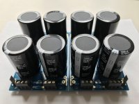
Here is a photo of the resistors and pots installed on the board:

Before I move onto the next step, I would appreciate any feedback on my measurements. I did re-check everything and I believe the differences are due to using the 1 kohm pots instead of the 500 ohm pots for P3 and P4.
Going through the initial resistance measurements, I found some of my measurements to deviate from Nelson Pass' document. I had all pots set in their halfway positions.

Here is a photo of the resistors and pots installed on the board:

Before I move onto the next step, I would appreciate any feedback on my measurements. I did re-check everything and I believe the differences are due to using the 1 kohm pots instead of the 500 ohm pots for P3 and P4.
I am finally getting around to building the Sony VFET P-P amp. I carefully measured and matched the resistors and capacitors, and I populated the boards following the schematic. One deviation from the schematic is the use of Bourns 1 kohm pots for P3 and P4 (PN 652-3386P-1-102LF) and Bourns 5 kohm pots for P1 and P2 (PN 652-3386P-1-502). This should allow me to properly set the bias high enough for FQP MOSFETs instead of the 2SK and 2SJ MOSFETS.
Going through the initial resistance measurements, I found some of my measurements to deviate from Nelson Pass' document. I had all pots set in their halfway positions.
View attachment 716349
Here is a photo of the resistors and pots installed on the board:
View attachment 716350
Before I move onto the next step, I would appreciate any feedback on my measurements. I did re-check everything and I believe the differences are due to using the 1 kohm pots instead of the 500 ohm pots for P3 and P4.
I have been trying to help Rich on his build, I sold him the V-fet's I bought from Acroman years ago, and my understanding is that after he adjusted the pots some the numbers did get closer to the specified ones Nelson posted. Any other opinions, advice, suggestions on his build will be much appreciated from other members who have built this amplifier.
Hi Rich,
Hopefully others will chime in but I too think your differences are due to the use of
the 1K pot.
Cheers,
Dennis
Hopefully others will chime in but I too think your differences are due to the use of
the 1K pot.
Cheers,
Dennis
Thanks for the help wdecho and Dennis. I am open to input from others. This is not the first amp I’ve built, but it is the first Pass DIY amp I’ve taken on.
Looks like you need to join the ground planes to make it a bipolar supply
See diyAudio Power Supply Circuit Board v3 illustrated build guide for reference.
See diyAudio Power Supply Circuit Board v3 illustrated build guide for reference.
I have to order all the hardware for assembling the Sony VFET amp into a 4U Deluxe Chassis from the diyAudio store. Since I don’t have a complete kit, does anyone have a complete list of the hardware required to assemble the T-brackets to the heat sinks and other hardware used for mounting all of the semiconductors (MOSFETs, diodes, etc. onto the chassis.
I countacted the store, and they do not have any extra hardware sets for the Sony VFET kit.
Thanks in advance,
I countacted the store, and they do not have any extra hardware sets for the Sony VFET kit.
Thanks in advance,
I was curious if anyone here who has built themselves one of these VFet amps has also heard a production model First Watt J2? If anyone has, could they shed some light as to how these amps sound differently from one another? What are the pro's for each amp?
I have to order all the hardware for assembling the Sony VFET amp into a 4U Deluxe Chassis from the diyAudio store. Since I don’t have a complete kit, does anyone have a complete list of the hardware required to assemble the T-brackets to the heat sinks and other hardware used for mounting all of the semiconductors (MOSFETs, diodes, etc. onto the chassis.
I countacted the store, and they do not have any extra hardware sets for the Sony VFET kit.
Thanks in advance,
The holes drilled in the Deluxe 4U heatsinks are metric. I forget the correct size but the deluxe 4U will have metric bolts and nuts to assembly the chassis with extras you can use to figure out what size you need. Homedepot, Lowe's etc carry metric bolts and nuts. I buy the 4U without drilled holes in the heatsink and drill and tap mine to SAE threads when I installed the bracket. Perhaps someone that has bought the deluxe chassis will give you an answer on what the correct metric bolt size and thread is. You really do not need the kit with some shopping at hardware stores.
Last edited:
Thanks guys. I re-read this thread and found the following post:
https://www.diyaudio.com/forums/pass-labs/302380-sony-vfet-illustrated-build-guide-45.html#post5319518
I purchased some kits for M3 Brass standoffs and M3 stainless steel machine screws, washers and nuts from Amazon.com, so I’m all set.
I should be all set to complete this amp just in time for the holidays next month.
You'll love it when you are done. It's my favorite of the Pass amps that I've built. (F5, Aleph j, F6, M2)
For this Thanksgiving, I am grateful that wdecho sold me his spare Sony VFETs, Pass DIY PCBs and mounting brackets. I’ve always wanted to build a Pass DIY First Watt amplifier, and I think will be a special project considering the positive reviews that many have posted. To be honest, I’ve avoided building many of the Pass DIY amps, because I’ve seen the slippery slope. Oh well.
- Home
- Amplifiers
- Pass Labs
- Sony vFET Illustrated build guide

