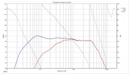
I did a quick mock-up in XSim using ideal drivers. The tranfer functions don't look too unreasonable actually. I still think this crossover went with different drivers altogether.
Did Sonus have another 3 way speaker at the time?
I have also attached the XSim crossover file in case anyone wants to take this further.
Best,
Erk
Did Sonus have another 3 way speaker at the time?
I have also attached the XSim crossover file in case anyone wants to take this further.
Best,
Erk
Attachments
Last edited:
I think Nikon is in a pretty happy place here. 😀
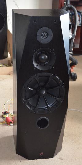
This Sonus Faber Grand Piano Domus is physically a nice speaker:
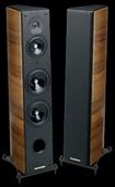
Some issues with the frequency response, but nothing unfixable to a dedicated diy enthusiast.
Drivers seem to be this:
H1217-08 CA18RLY
H1216-08 CA15RLY
And a Vifa XT25 or SS R2604 ring radiator, which we know all about.
The more efficient H1262-08 MCA15RCY might solve all the midrange issues.
Poor Man'
Nikon is clearly someone willing to work at it. Success is assured.
This Sonus Faber Grand Piano Domus is physically a nice speaker:
Some issues with the frequency response, but nothing unfixable to a dedicated diy enthusiast.
Drivers seem to be this:
H1217-08 CA18RLY
H1216-08 CA15RLY
And a Vifa XT25 or SS R2604 ring radiator, which we know all about.
The more efficient H1262-08 MCA15RCY might solve all the midrange issues.
Poor Man'
Nikon is clearly someone willing to work at it. Success is assured.
Steve,
Those look like really nice drivers, how do you screw them up that badly? 😀 Was the midrange in too small of an enclosure?
Those look like really nice drivers, how do you screw them up that badly? 😀 Was the midrange in too small of an enclosure?
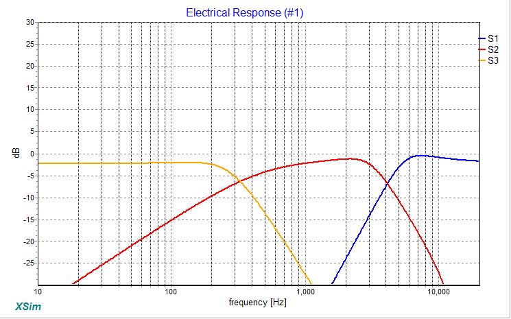
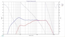
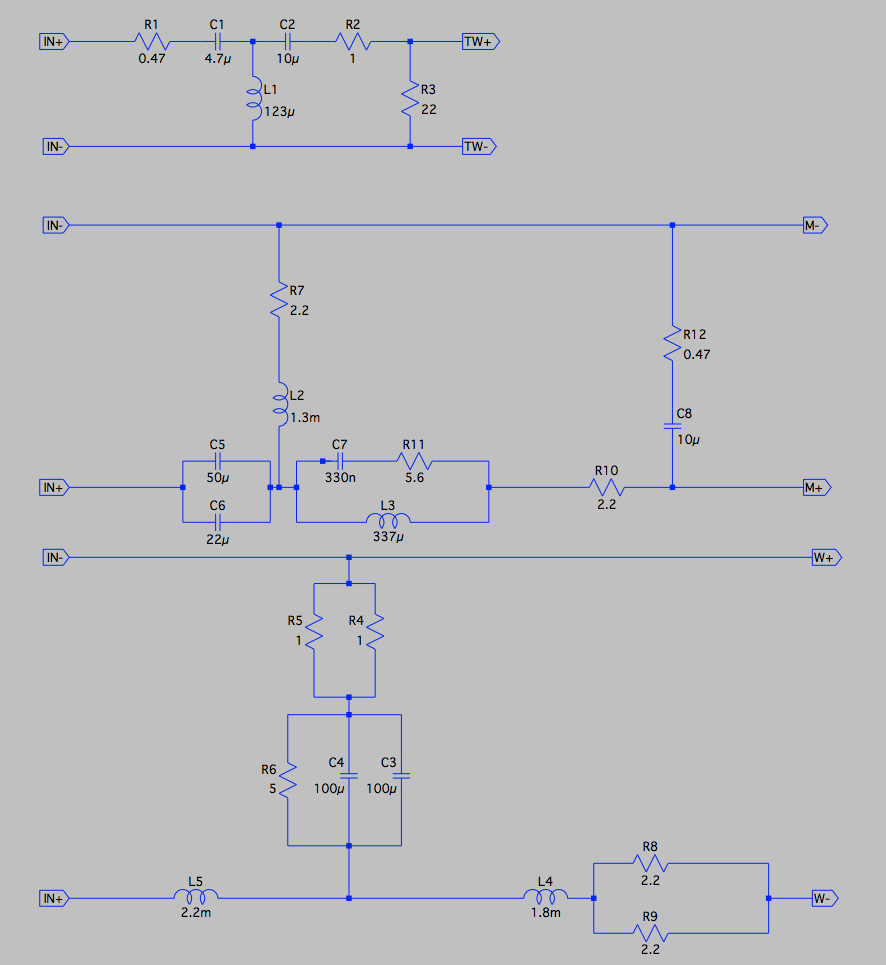
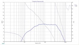
OK, I clearly have no life at all outside of this forum, and to prove it I used SPL Copy to import the data I could find thanks to Steve. Here is the output based on the crossover values and the traced driver data. Driver delay is assumed to be 0. Drivers were phase restored using OmniMic:
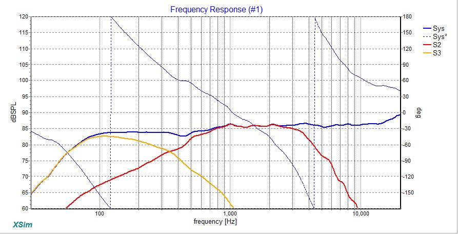
This makes no sense. I mean, first the crossover appears ideal for the drivers with no time offset. Also, it's pretty damn flat. Where's the W shaped humps? The only thing I can think of, is we have the wrong drivers, or the cabinet volumes are all messed up?
This makes no sense. I mean, first the crossover appears ideal for the drivers with no time offset. Also, it's pretty damn flat. Where's the W shaped humps? The only thing I can think of, is we have the wrong drivers, or the cabinet volumes are all messed up?
Attachments
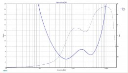
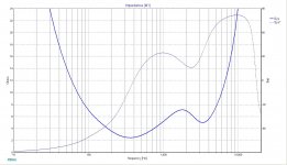
The impedance plots I have gotten are very very low, but also very flat. Again, I'm just going to go scratch my head for a while.
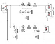
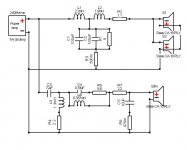
Oops, OK, I forgot the dual woofer thing. I assume in parallel? Doesn't hurt at all, but here's the final XO design if anyone wants to play with it.
Yes, woofers are in parallel
So, it looks like we have two options: working on the crossover or on crossover and drivers. The thing we do not have info about drivers. I think they are prestige series, but custom made. What measurements can I do to have a full picture?
Thanks to everybody for help.
D
Thanks to everybody for help.
D
So, it looks like we have two options: working on the crossover or on
crossover and drivers. What measurements can I do to have a full picture? D
Drivers are fine. You could search older threads on loudspeaker measurements
and spreadsheet simulators to find out what's going on and how to improve it.
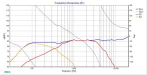
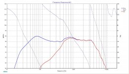
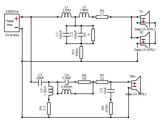
I have prepared a sim that at least resembles somewhat to measurement you
provided. It wouldn't take much of your time to try 2 mods. First is to cut the
wire between 2R2 and 1,3mH which might improve the sound in woofer-
midrange part of the spectrum or a second one to bypass the 72uF(50+22)
with a 150 uF NPE.
Attachments

Davide,
I think the small midrange enclosure plays an important role in your speaker and has to be taken into account in order to do a proper simulation.
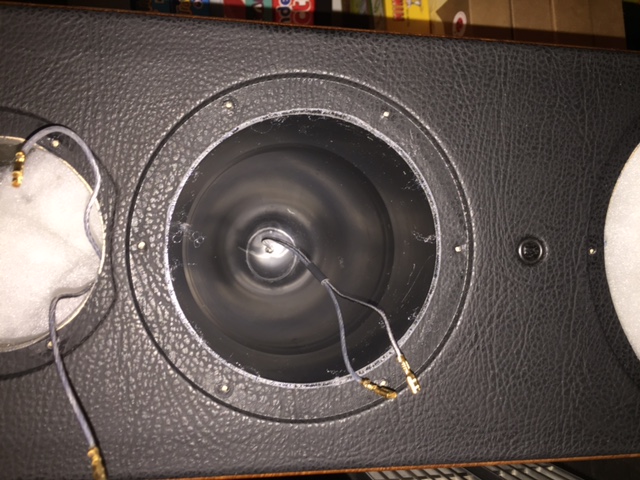
It's difficult to see on the picture, diameter around 113 mm, what's the depth?
I think the small midrange enclosure plays an important role in your speaker and has to be taken into account in order to do a proper simulation.
It's difficult to see on the picture, diameter around 113 mm, what's the depth?
Always a pleasure to read Dissi, he's someone I trust on these sort of things. I believe he designs simulators. 🙂
Lojzek, TBH, I'm a bit dubious about what you have done here.
Is it a good idea to work the mid harder here? Surely if there is a bass issue, it lies with the bass filter. Two 6" basses can hardly be stressed.
IMO, the mid filter could do with some change, but not by lowering its crossover point. The whole 3 way idea is to save the mid any bass duties, thus lowering distortion.
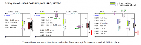
Troels Gravesen's 3 way classic uses wildly different mid crossover values.
SEAS-3-Way-Classic. Below.
We don't know what the drivers are exactly, but certainly a SEAS 5" mid without dustcap, which may explain the midrange hole. The exact SEAS 6" basses aren't mission critical IMO. Woofers are woofers.
My feeling is that plugging the reflex port is good to reduce an apparently lumpy bass.
Without knowing much about the drivers, I feel that a simplified bass crossover and the reflex mod will largely fill the hole. Easily doable. The mid, I can leave for another day. There may be some level adjustments required for a good balance too. A little bit of scope there.
Lojzek, TBH, I'm a bit dubious about what you have done here.
Is it a good idea to work the mid harder here? Surely if there is a bass issue, it lies with the bass filter. Two 6" basses can hardly be stressed.
IMO, the mid filter could do with some change, but not by lowering its crossover point. The whole 3 way idea is to save the mid any bass duties, thus lowering distortion.
Troels Gravesen's 3 way classic uses wildly different mid crossover values.
SEAS-3-Way-Classic. Below.
We don't know what the drivers are exactly, but certainly a SEAS 5" mid without dustcap, which may explain the midrange hole. The exact SEAS 6" basses aren't mission critical IMO. Woofers are woofers.
My feeling is that plugging the reflex port is good to reduce an apparently lumpy bass.
Without knowing much about the drivers, I feel that a simplified bass crossover and the reflex mod will largely fill the hole. Easily doable. The mid, I can leave for another day. There may be some level adjustments required for a good balance too. A little bit of scope there.
Attachments
Last edited:
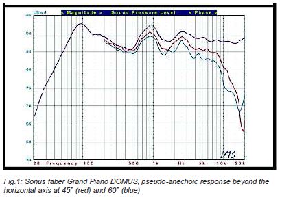
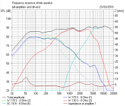
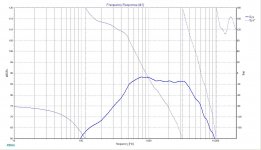
I've been sitting on the sidelines with my popcorn watching the development of this thread and I'm beginning to wonder if we have a chicken and egg (which came first) scenario. Did the OP find this LMS measurement before deciding his speakers didn't sound right, or did he seek out some test data after deciding he didn't like the sound of his speakers?
Here we have a single data point with the LMS test and can find no other authoritative test results on the web. Does the OP's speaker measure the same? Others here have encouraged the OP to acquire test gear to answer that question and I agree with that suggestion. No doubt there is a lot of talent who visits here with a willingness to help with this type of issue, but the old computer adage: 'garbage in = garbage out' lurks in the background because the OP hasn't the ability to get the data needed for a correct sim and solution to his request for an XO redesign. It's all speculation until that data is obtained or more (LMS) supportive, independent FR test data can be found.
Here we have a single data point with the LMS test and can find no other authoritative test results on the web. Does the OP's speaker measure the same? Others here have encouraged the OP to acquire test gear to answer that question and I agree with that suggestion. No doubt there is a lot of talent who visits here with a willingness to help with this type of issue, but the old computer adage: 'garbage in = garbage out' lurks in the background because the OP hasn't the ability to get the data needed for a correct sim and solution to his request for an XO redesign. It's all speculation until that data is obtained or more (LMS) supportive, independent FR test data can be found.
I do that apparently shameful thing of using my ears. 😀
And use a vague understanding of what does what in a crossover to adjust it.
Anybody remember the woefully bad Wilmslow Audio Prestige project?
http://www.diyaudio.com/forums/multi-way/210627-wilmslow-audio-prestige-platinum-72.html#post4326410
Great and expensive drivers, but an apparently random crossover and tonal balance. But IMO, crossovers are an established technology. We aim for Steen Duelund curves and it mostly works out. This is our hope and expectation. 😱
Attachments
It actually all started from my perception that things were not quite right in the listening test. This was supported also by some other educated listeners.
With guidance I am happy to embark in measurements. I'll try to get access to an established measurement setup. I am not home this week, so I'll have to wait next week. I am very glad to see that there is a solution out there.
I don't know if the following is possible, but if with a new crossover setup we would manage to achieve an higher impedance, this would make the life of my amps much easier.
Davide
You are right, as is usually the case. 🙂
My attempts at simulation were just to see where things would be if optimal. Often simulations and models provide a best case scenario, and when our real world examples don't match it is when we go looking for ways to improve.
This is one of those cases, I think. 🙂
Measurements of the drivers in situ should be next. I'm very curious to see just how you make a W shaped curve out of those drivers. 🙂
Best,
Erik
I've been sitting on the sidelines with my popcorn watching the development of this thread and I'm beginning to wonder if we have a chicken and egg (which came first) scenario. Did the OP find this LMS measurement before deciding his speakers didn't sound right, or did he seek out some test data after deciding he didn't like the sound of his speakers?
Here we have a single data point with the LMS test and can find no other authoritative test results on the web. Does the OP's speaker measure the same? Others here have encouraged the OP to acquire test gear to answer that question and I agree with that suggestion. No doubt there is a lot of talent who visits here with a willingness to help with this type of issue, but the old computer adage: 'garbage in = garbage out' lurks in the background because the OP hasn't the ability to get the data needed for a correct sim and solution to his request for an XO redesign. It's all speculation until that data is obtained or more (LMS) supportive, independent FR test data can be found.
Lojzek, TBH, I'm a bit dubious about what you have done here.
Is it a good idea to work the mid harder here? Surely if there is
a bass issue, it lies with the bass filter. Two 6" basses can hardly
be stressed.
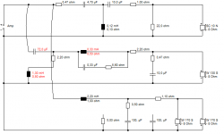
My suggestion was supposed to be an easy to do modification.
I could have said something about increasing the value of 1,3mH
which would make the XO point higher(Impedance benign), but it
wouldn't have been practical for the purpose I had in mind. It's true
that the 220uF mod lowers the total impedance but that would
be remedied in case OP found it audibly better. Nothing final here.
Just fun.
Attachments
- Status
- Not open for further replies.
- Home
- Loudspeakers
- Multi-Way
- Sonus Faber Grand Piano Domus