Try measuring the impedance of each driver(in a box) without any
filters attached. When you do that we'll proceed further with measuring
drivers separately in a way that we can load these measurements
to a simulator. Use some kind of smoothing to you measurements
so it's easier to look at. Something like 1/12th or 1/6 th.
filters attached. When you do that we'll proceed further with measuring
drivers separately in a way that we can load these measurements
to a simulator. Use some kind of smoothing to you measurements
so it's easier to look at. Something like 1/12th or 1/6 th.
Try measuring the impedance of each driver(in a box) without any
filters attached. When you do that we'll proceed further with measuring
drivers separately in a way that we can load these measurements
to a simulator. Use some kind of smoothing to you measurements
so it's easier to look at. Something like 1/12th or 1/6 th.
Driver DC resistances would suffice, wouldn't they? Just to make sure there are no obvious pratfalls here...
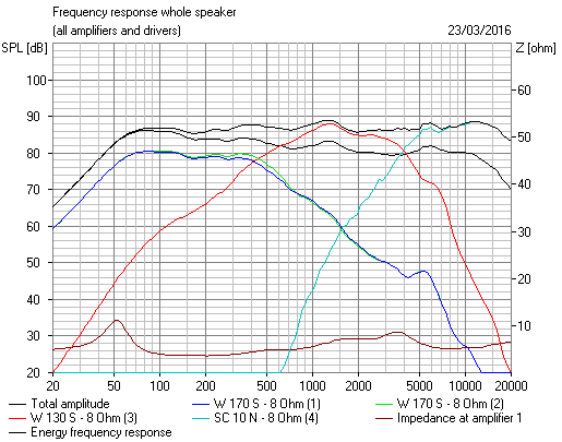
I'm seeing a correlation between the measurements here:
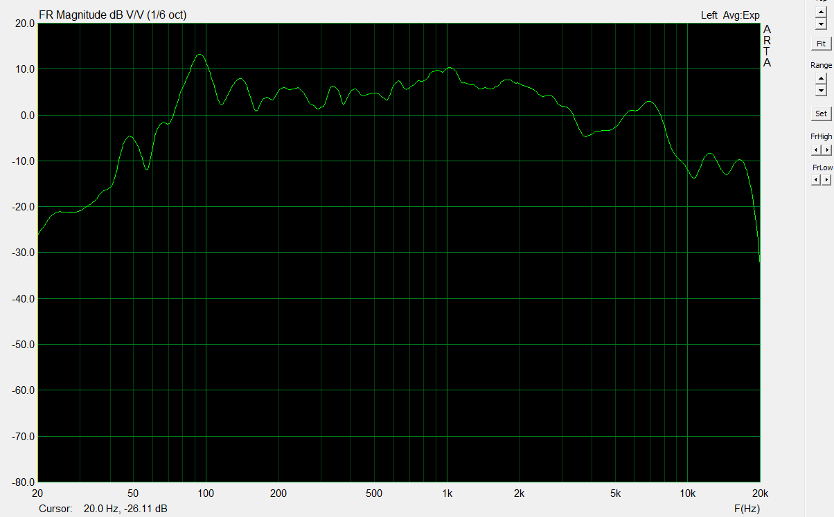
Really the question for you is WHAT IS WRONG WITH THEM?
I'm seeing too much bass and some dips in the midrange and too much tweeter rolloff. What are you hearing?
I measured the DCR and impedance at various frequency of the drivers. I did not have time to use the spectrum analyzer to make a full plot, but my LCR meter allows me to use 100 Hz, 120 Hz, 1kHz, 10 KHz.
Here are the results:
DCR 100 Hz 120 Hz 1KHz 10 kHz
Woofer down 5.8 13.2 9.2 8.6 26
Woofer up 5.8 13.9 9.4 8.6 25.5
Midrange 5.2 8.3 10.8 7.4 24.3
Tweeter 3.2 5.6 4.0
I'd really love to have the woofer in series rather than in parallel, it would make the life of my amps much easier.
Thanks,
Davide
Here are the results:
DCR 100 Hz 120 Hz 1KHz 10 kHz
Woofer down 5.8 13.2 9.2 8.6 26
Woofer up 5.8 13.9 9.4 8.6 25.5
Midrange 5.2 8.3 10.8 7.4 24.3
Tweeter 3.2 5.6 4.0
I'd really love to have the woofer in series rather than in parallel, it would make the life of my amps much easier.
Thanks,
Davide
Last edited:

Really the question for you is WHAT IS WRONG WITH THEM?
1) With the port open, I definitely would say boomy basses. I find interesting to see that the port affects mostly below 100 Hz.
2) In general I would say that the sound is closed and the instrument "disconnected" between each other.
It's difficult to verbalize.
To experiment with new crossovers, I am more inclined to make new one from scratch, even if I will spend a bit more. The components are glued to the board and to try to reuse them would be a potential destructive operation.
Thanks,
Davide
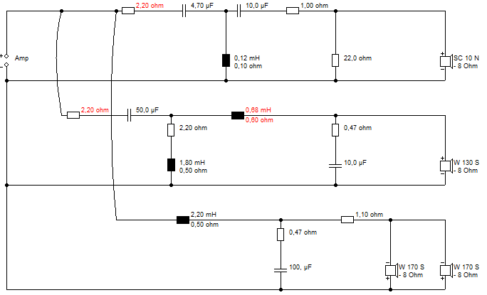
Once again I'll put a marker down so I can remember what we are doing here:
Somehow I thought this sort of thing was better:
The bass circuit can be adjusted in situ IMO. Quite easy in fact. Bit of unsoldering with that copper braid to soak it up, and solder a piece of 20-30A fuse wire (it's tinned copper really...) across the second coil. Quite reversable too. And I thought the port was best closed anyway.
Maybe some level adjustment later on tweet and mid, but the only other thing was to remove the tank and increase to 0.68mH in the mid. There was also the thought of putting the 1.8mH in the mid and unsoldering the 22uF. But I'd do the bass section first, and have a listen.
That's only hot glue, my friend. It peels off a PCB with a blade. It comes off with hot water. Messy job, but doable. Most components are waterproof and safe up to 85C. But I might try to keep the electolytics from water. And you can buy new nylon zip ties easily enough. Nothing hard there at all, IMO.
Last edited:
I'll give you some tips aside from Troels' advice:
Tips and ideas Copyright 2012-14
Get a 40W iron and tin it the very first time it warms up. Apply heat for about 5 seconds, no more. If it's not working, pull out and blow on the component to cool it down.
Coils and resistors are tough as old boots, but capacitors should be worked on quickly and decisively to avoid heat damage.
Coils use enamelled wire, so if you need to strip off a turn for more wire, you must scrape the enamel off with a blade.
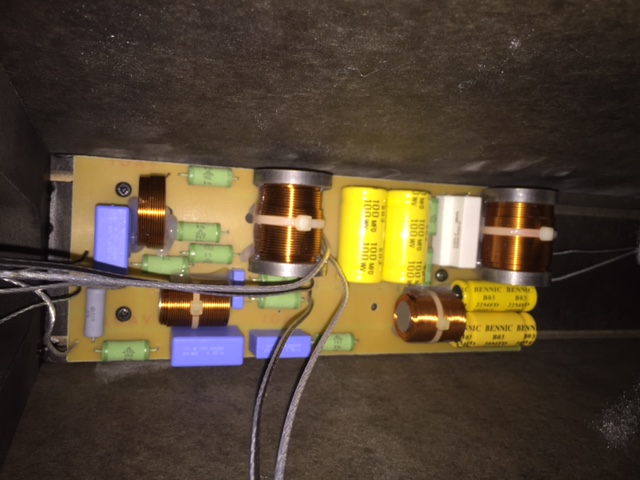
It's good to study the filter and board so you have a good grasp of what goes where and how you might fit in extra stuff. Nothing stopping you drilling more holes or adding connections. One of mine, below.
Tips and ideas Copyright 2012-14
Get a 40W iron and tin it the very first time it warms up. Apply heat for about 5 seconds, no more. If it's not working, pull out and blow on the component to cool it down.
Coils and resistors are tough as old boots, but capacitors should be worked on quickly and decisively to avoid heat damage.
Coils use enamelled wire, so if you need to strip off a turn for more wire, you must scrape the enamel off with a blade.
It's good to study the filter and board so you have a good grasp of what goes where and how you might fit in extra stuff. Nothing stopping you drilling more holes or adding connections. One of mine, below.
Attachments
Nikon,
If I were you, I would leave the original filters as is. Build new filters, then you have the option to keep speakers intact if you want to sell them. If you're dabbling with dumpster finds that's ok, but these SF is worth a bit more.....
Peter
If I were you, I would leave the original filters as is. Build new filters, then you have the option to keep speakers intact if you want to sell them. If you're dabbling with dumpster finds that's ok, but these SF is worth a bit more.....
Peter
Nikon,
If I were you, I would leave the original filters as is. Build new filters, then you have the option to keep speakers intact if you want to sell them. If you're dabbling with dumpster finds that's ok, but these SF is worth a bit more.....
Peter
+1 sound advice. No pun intended.
Well,
I think that to play with the bass, at least with one speaker I can do without doing more damage. One of the 2.2 mH coil is already detached and can be reused.
So I could put together a bass section as I have the other components. I have 1 ohm instead of 1.1 ohm.
For the 100 uF I have some big polypropylene caps or some electrolytic. Would the first type be OK ? In any case I would have no problem in desoldering the caps. These are not glued.
D.
Why do you need ANY new components to modify the bass filter? 😕
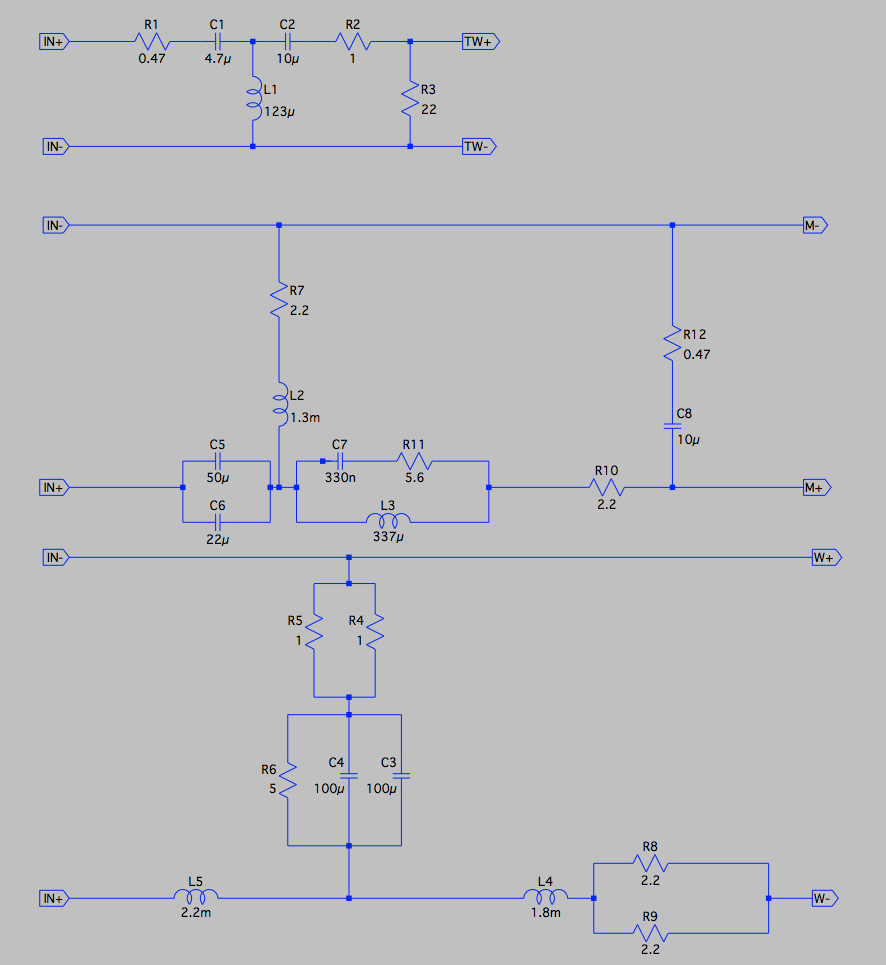
You do realise that two existing 1R resistors in parallel make the 0.47R in my schematic? And the 1.1R is just two 2.2R in parallel. I did try to make it easy for you. 😎
You do realise that two existing 1R resistors in parallel make the 0.47R in my schematic? And the 1.1R is just two 2.2R in parallel. I did try to make it easy for you. 😎


Ready for testing. I also managed to put the 2.2 ohm on mid and tweeter. Probably testing tomorrow, let's hope in good weather🙂
D
Davide, this is good! Truly diy! 😀
So we're mostly going for the whole thing here?
And not complete without some idea of what is going on:
Now it is good to totally disconnect the redundant bass crossover section when disconnecting drivers, because they become resonant without a load, but I guess that is done.
Give it a good listen, because it takes a couple of hours for your ears to really pick out the good and the bad. Tweeter level was some psychic guess by me, I could have got it wrong, so the red resistors are select on test. Generally every 1 ohm makes 1dB difference. I think I mainly did things to them to raise the impedance and make this amp friendly.
Last edited:
The 2.2 ohm resistor is made with two 1ohm + one 0.22 ohm in series, so I can ply with the value. It's one for both mid and tweeters. The bass crossover is disconnected, as I reused the big coil.
I will have possibility to listen one speaker only, the second is intact.
If I want to purchase the 0.68 mH what awg should I pick
Thanks,
Davide
I will have possibility to listen one speaker only, the second is intact.
If I want to purchase the 0.68 mH what awg should I pick
Thanks,
Davide
I did a quick listen today: with the new filter it sounds a bit like behind a curtain and bass are less under control. I kind of like the extra brightness when I short the 2.2 ohm resistor. More to come.
Davide
Davide
Forget my comment: I had forgotten to solder back the legs of some of the coils.
Let's do it again.
D
Let's do it again.
D
Davide, the 2.2R resistors are holding up the impedance to amp-friendly levels, so you might be taking a chance here. 🙂
Did I recommend a modelling program?
Downloads
boxsim-db.de | Boxsim Projektdatenbank
Import something similar with 4 drivers into the projekte folder then modify it to resemble your speaker. Even if the drivers have different frequency response, they should behave electrically much the same.
Then you become a light unto yourself, as they say. Anything below 4 ohms is generally bad. Only YOU can decide how it sounds, at what frequency the problem is occurring, and what to do about it. Is it the bass, the midbass, the mids or the top end? FWIW, the high notes on electric guitar are about 1.5kHz, for instance, the twangy harmonics are higher. Female voices are about 1kHz usually.
- Status
- Not open for further replies.
- Home
- Loudspeakers
- Multi-Way
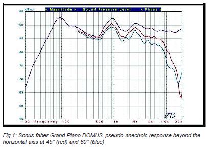
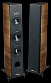
- Sonus Faber Grand Piano Domus