TubeHEX+
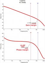
Feedback loop AC analysis and closed loop Bode plot.
ULGF ~ 2MHz
Phase margin ~ 76 degrees
Gain margin ~ 21 db
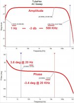
1Hz - 500KHz bandwidth @ -3 db level
3.6 deg phase shift @ 20 Hz
3.4 deg phase shift @ 20 KHz (negative)
Pretty cool 😎
Feedback loop AC analysis and closed loop Bode plot.
ULGF ~ 2MHz
Phase margin ~ 76 degrees
Gain margin ~ 21 db
1Hz - 500KHz bandwidth @ -3 db level
3.6 deg phase shift @ 20 Hz
3.4 deg phase shift @ 20 KHz (negative)
Pretty cool 😎
Attachments
I've just finished doing some noise and distortion testing on my VHex+ amplifier. This is a complete stereo amplifier with simple dual supplies and a single main transformer under noisy florescent light in real world conditions.
At 1W output THD
1kHZ 0.0039%
10kHZ 0.0079%
20kHZ 0.013%
At 50W output into 8 ohm dummy loads
1kHZ 0.0059%
Noise floor with open inputs 0.17mV
Noise floor with shorted inputs 0.08mV
I'm very impressed with this little amplifier!
At 1W output THD
1kHZ 0.0039%
10kHZ 0.0079%
20kHZ 0.013%
At 50W output into 8 ohm dummy loads
1kHZ 0.0059%
Noise floor with open inputs 0.17mV
Noise floor with shorted inputs 0.08mV
I'm very impressed with this little amplifier!
Very cool!  Better than I expected 😛
Thank you for arranging those independent measurements - it's always interesting to see the performance of a "production version" build.
Assuming, the maximum output swing is 28V RMS, the noise floor of 0.08mV lays 110dB below it.
Pretty much in line with what I saw on my spectrums. Dead silent at idle. 2N5089 - excellent input devices.
Bearing in mind overall simplicity and rather low cost - it's a good one!
Perfect for everyday use in home audio system.
Shall we make an integrated version? Some 3 inputs, volume pot, remote control... or a separate preamp. Or both 😀
Better than I expected 😛Thank you for arranging those independent measurements - it's always interesting to see the performance of a "production version" build.
Assuming, the maximum output swing is 28V RMS, the noise floor of 0.08mV lays 110dB below it.
Pretty much in line with what I saw on my spectrums. Dead silent at idle. 2N5089 - excellent input devices.
Bearing in mind overall simplicity and rather low cost - it's a good one!
Perfect for everyday use in home audio system.
Shall we make an integrated version? Some 3 inputs, volume pot, remote control... or a separate preamp. Or both 😀
I've got a great little preamp running with three inputs and a headphone amp onboard and PGA23xx volume control. Buffers are op amps though. I think this thing deserves a discrete Ampliwire linestage.
It would be simple enough to build this into an integrated amp, or a matching preamp would be nice too. I think the latter would be better at these noise levels.
It would be simple enough to build this into an integrated amp, or a matching preamp would be nice too. I think the latter would be better at these noise levels.
Hi Jeff, Valery,
When I saw those numbers, I was also very pleased with the performance. That amplifier was basically immune to the florescent lights that put out a nasty amount of noise around 28, 56 and 84 KHz. I just stuck a wire into my audio FFT analyzer (HP 35665A Signal Analyzer) and got those approximate numbers. Jeff turned off the lights and we saw very little difference in the THD readings using only the 400 Hz high pass and 80 KHz low pass filters. That is excellent noise rejection and one of the best I have seen on this bench.
Of course we used properly shielded signal leads, but the speaker loads were connected by a zip-wire style cable, #16 gauge wire. The loads were 8R 250 watt Dale dummy loads, the industry standard. The test setup represents connections that would exist with decent quality RCA signal cables and your average speaker wire. So these tests do not represent some unattainable setup, but rather performance that anyone would expect to see from their own setup.
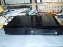
This amplifier is pretty to look at as well. I wouldn't have any problem looking at it in my system, that's for sure. These are real performance numbers measured on my bench without any connection between me and Valery's efforts. Jeff simply asked if I would measure the amplifier, and I didn't even know what amplifier I would be looking at. So there you go.
Too bad the picture I took doesn't do this amplifier justice. It's more shiny and deep black than it looks, and my bench is a disaster zone. But, here it is!
Great job guys! -Chris
When I saw those numbers, I was also very pleased with the performance. That amplifier was basically immune to the florescent lights that put out a nasty amount of noise around 28, 56 and 84 KHz. I just stuck a wire into my audio FFT analyzer (HP 35665A Signal Analyzer) and got those approximate numbers. Jeff turned off the lights and we saw very little difference in the THD readings using only the 400 Hz high pass and 80 KHz low pass filters. That is excellent noise rejection and one of the best I have seen on this bench.
Of course we used properly shielded signal leads, but the speaker loads were connected by a zip-wire style cable, #16 gauge wire. The loads were 8R 250 watt Dale dummy loads, the industry standard. The test setup represents connections that would exist with decent quality RCA signal cables and your average speaker wire. So these tests do not represent some unattainable setup, but rather performance that anyone would expect to see from their own setup.
This amplifier is pretty to look at as well. I wouldn't have any problem looking at it in my system, that's for sure. These are real performance numbers measured on my bench without any connection between me and Valery's efforts. Jeff simply asked if I would measure the amplifier, and I didn't even know what amplifier I would be looking at. So there you go.
Too bad the picture I took doesn't do this amplifier justice. It's more shiny and deep black than it looks, and my bench is a disaster zone. But, here it is!
Great job guys! -Chris
Attachments
Last edited:
I basically have same amp and find it is even quieter with Abletec SMPS and CRC filter compared to linear 300VA trabsformer. Great little amp and my main reference for my system.
I've just finished doing some noise and distortion testing on my VHex+ amplifier. This is a complete stereo amplifier with simple dual supplies and a single main transformer under noisy florescent light in real world conditions.
At 1W output THD
1kHZ 0.0039%
10kHZ 0.0079%
20kHZ 0.013%
At 50W output into 8 ohm dummy loads
1kHZ 0.0059%
Noise floor with open inputs 0.17mV
Noise floor with shorted inputs 0.08mV
I'm very impressed with this little amplifier!
Dear Wilhelm,
Thank you very much for the clear post of the test results of VHex+ amplifier. Went searching in the previous 80 odd posts for the schematic of VHex+, but could not find it. With so many sons floating around, it will be easy if you kindly give a reference to the actual schematic or at least post number to avoid confusion. The best will be if you post the schematic itself. Thanking you.
--gannaji
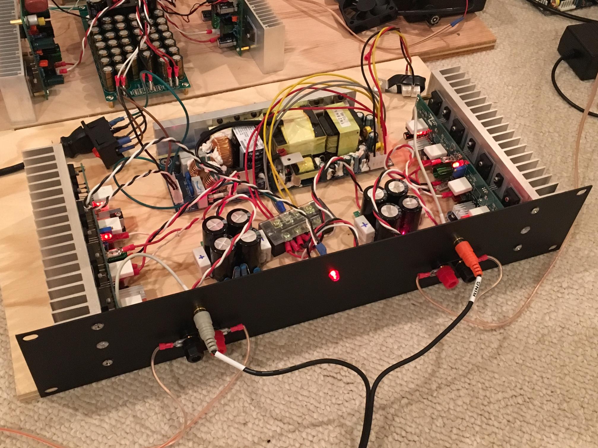
Here's the schematic for this version of the amplifier.
I plan to take real world measurements of all of these as I get prototypes into chassis. I see many tests of amplifiers sprawled out on a test bench, but I don't think this is really an accurate way to test an amplifier. Noise immunity is really tested more accurately when it's stuffed into a chassis along with another channel and a power supply.
Attachments
Hi Jeff, Valery,
When I saw those numbers, I was also very pleased with the performance. That amplifier was basically immune to the florescent lights that put out a nasty amount of noise around 28, 56 and 84 KHz. I just stuck a wire into my audio FFT analyzer (HP 35665A Signal Analyzer) and got those approximate numbers. Jeff turned off the lights and we saw very little difference in the THD readings using only the 400 Hz high pass and 80 KHz low pass filters. That is excellent noise rejection and one of the best I have seen on this bench.
Of course we used properly shielded signal leads, but the speaker loads were connected by a zip-wire style cable, #16 gauge wire. The loads were 8R 250 watt Dale dummy loads, the industry standard. The test setup represents connections that would exist with decent quality RCA signal cables and your average speaker wire. So these tests do not represent some unattainable setup, but rather performance that anyone would expect to see from their own setup.
This amplifier is pretty to look at as well. I wouldn't have any problem looking at it in my system, that's for sure. These are real performance numbers measured on my bench without any connection between me and Valery's efforts. Jeff simply asked if I would measure the amplifier, and I didn't even know what amplifier I would be looking at. So there you go.
Too bad the picture I took doesn't do this amplifier justice. It's more shiny and deep black than it looks, and my bench is a disaster zone. But, here it is!
Great job guys! -Chris
Chris, many thanks for the tests!
You've got some nice gear in the lab
I think, we will go for some AP device for Jeff for instant testing all the things he builds over the time 😉
Cheers,
Valery
Having this sort of equipment on hand would be a great asset when assembling the amplifier. being able to measure different wire routing options as opposed to just looking at it and trying to guess the quietest solution would be nice. Aiming a leaky toroidal transformer would be much easier too.
I really want an amp measurement rig! Planning to use nice low HD low noise sound card (Focusrite Scarlett 2i2) and REW. Hope these specs are good enough.
2nd gen:
https://us.focusrite.com/usb-audio-interfaces/scarlett-2i2
2nd gen:
https://us.focusrite.com/usb-audio-interfaces/scarlett-2i2
Hi Jeff, Valery,
You would probably be best using something along the lines of an HP 339A or 334A for the front end, with the monitor output into a spectrum analyzer. I happen to use an HP 35665A, but an HP 3585 would also work (up to 40 MHz) so that oscillations would also be visible. You really want to look at distortion and the spectrum when dealing with lead dress and routing. In the mean time, Jeff is welcome to use my bench as the need arises. Don't forget that any spectrum analyzer requires a front end that can take very large AC voltages, which leaves your range on the spec-an mostly at one setting.
-Chris
Hi xrk971,
Same recommendation for you. You need some kind of "front end" on your sound card so you don't destroy it.
-Chris
Same recommendation for you. You need some kind of "front end" on your sound card so you don't destroy it.
-Chris
Can one DIY a front end? Basically a very low noise and low distortion preamp with over voltage limit on outputs right?
Hi Jeff, Valery,
You would probably be best using something along the lines of an HP 339A or 334A for the front end, with the monitor output into a spectrum analyzer. I happen to use an HP 35665A, but an HP 3585 would also work (up to 40 MHz) so that oscillations would also be visible. You really want to look at distortion and the spectrum when dealing with lead dress and routing. In the mean time, Jeff is welcome to use my bench as the need arises. Don't forget that any spectrum analyzer requires a front end that can take very large AC voltages, which leaves your range on the spec-an mostly at one setting.
-Chris
Totally agree with regards to the front-end.
I was using a simple divider at the input of Lynx L22 card-based measurement system and basically the same calibrated level of signals, measuring at 20V RMS output signal.
A proper front-end will give much more versatility and convenience.
This should be a decent analyzer. Jan Didden is also building an autoranger for it.
http://www.diyaudio.com/forums/equipment-tools/231401-quantasylum-qa400-qa401-223.html
Another one from the forum is
http://www.diyaudio.com/forums/equipment-tools/277808-diy-audio-analyzer-ak5397-ak5394a-ak4490.html
http://www.diyaudio.com/forums/equipment-tools/231401-quantasylum-qa400-qa401-223.html
Another one from the forum is
http://www.diyaudio.com/forums/equipment-tools/277808-diy-audio-analyzer-ak5397-ak5394a-ak4490.html
X,
i tried using Focusrite2i2 (not 2nd gen) for measurement, but i find it very noisy (USB isnt isolated so thats playing its role too). But a front end fixed divider is a start that was suggested to me as well.
saw some measurements with EMU 1616m and Praxis. That soundcard has very low noise levels and forms a potent combination with Praxis.
Note though EMU is not USB (needs PCIe) and Praxis is not supported anymore.
X,
i tried using Focusrite2i2 (not 2nd gen) for measurement, but i find it very noisy (USB isnt isolated so thats playing its role too). But a front end fixed divider is a start that was suggested to me as well.
saw some measurements with EMU 1616m and Praxis. That soundcard has very low noise levels and forms a potent combination with Praxis.
Note though EMU is not USB (needs PCIe) and Praxis is not supported anymore.
Hi Diyaudnut,
I used EMU 1616m during some time (still have it packaged in the box).
Lynx L22 is more expensive but far higher quality in terms of distortion, noise, bandwidth, etc.
Cheers,
Valery
Hi Diyaudnut,
I used EMU 1616m during some time (still have it packaged in the box).
Lynx L22 is more expensive but far higher quality in terms of distortion, noise, bandwidth, etc.
Cheers,
Valery
Hi Valery ,
What software do you use?
Do you have a quick scribble of the divider you used as front end for the lynx?
thanks
The software I'm using is WinAudioMLS from Dr. Jordan Design (Germany):
Audio Realtime Analyzer for Windows platform using FFT and MLS
Divider is 33k from the amp output to the card input, 1k from the card input to ground.
It gives me around 600mV RMS at the card input, having around 20V RMS at the amp output.
Cheers,
Valery
Audio Realtime Analyzer for Windows platform using FFT and MLS
Divider is 33k from the amp output to the card input, 1k from the card input to ground.
It gives me around 600mV RMS at the card input, having around 20V RMS at the amp output.
Cheers,
Valery
- Home
- Amplifiers
- Solid State
- Sons of VHex