Hi Jeff,
Hi MossFed,
Keep sharp for oscillation. It may only show up at signal peaks or the crossover area. The RF decoupling is a must!
-Chris
As expected ...When I tried using direct copper connection to the Trenchfet to aid cooling, it became unstable and showed some serious oscillation.
Hi MossFed,
Keep sharp for oscillation. It may only show up at signal peaks or the crossover area. The RF decoupling is a must!
-Chris
IRFP 260 is an N-channel MOSFET; but where did you find IRFP 9260?
Hi Sam,
My apologies, IRFP9240 and IRFP240.
A bit distraction last night when I burnt my midnight oil involving in an RF project.
Cheers and thanks for your rectification.
I was referring to my VTrench amplifier with Trenchfet output devices. When I tried using direct copper connection to the Trenchfet to aid cooling, it became unstable and showed some serious oscillation.
We are talking about difference capacitance, hi hi.
Mine as a capacitance to ground,
Yours was a positive feed back to input
Will try to avoid that kind of feedback by using small surface area and placing water jacket as far to the input stage as possible with small value capacitors shunted to ground
Cheers
Hi All, In both the original amp and this thread's improved one, the output stage uses two HEX FETs in parallel. When I used these ancient devices years ago, the gate turn on voltage could vary a volt or two with different brands and production date codes. The 0.22 ohm resistors at the source terminals would help match parallel bipolar transistors but don't drop enough voltage to help with this problem with FETs. Was there talk in the original thread about how to select matched FETs? IRF's semiconductor production tolerances may be tighter these days. Perhaps using devices with the same date/lot code is enough in most cases? Would be a shame for a constructor to get tripped up by this.
From what I've gathered the issue was with International Rectifier's versions of the device. As of late all versions I've found are Vishay, which don't have these issues. Voltage drop is very close on all my emitter resistors.
Same here. I normally test Vgs with my transistors tester, but it varies in the range of 3.5...3.6V for IRFP240, for example. Further voltage drop measurements over the source resistors show very close values as well.
I use 5 pairs of HexFETs per channel in one of my builds (other project) - no problem as well.
I use 5 pairs of HexFETs per channel in one of my builds (other project) - no problem as well.
I turned off my ad-blocking software so hopefully will get paragraphs now. Yes!
Checking the voltage drop across the "emitter" resistors is a good test. I would do it.
Keep in mind that HEX FETs and similar power MOSFETs are designed and sold for switching applications. Matching turn on voltage of parallel devices isn't needed when the device spends 99.9% of its time either ON or OFF. So it's not something semi manufacturers cared about. The IRF spec sheet for the 240 says Vthreshold is between 2 to 4 volts.
On the other hand, in my experience, if semiconductors come from the same lot, they can be well matched.
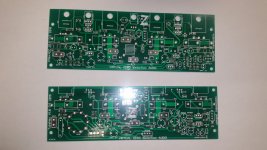
Nice boards!I've just received a couple new variations of the VHex for testing. Tube Hex and VHex+EC are waiting for assembly.😀
As usual...🙂
I've just received a couple new variations of the VHex for testing. Tube Hex and VHex+EC are waiting for assembly.😀
Looking good Jeff!
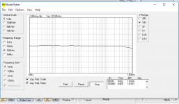
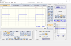
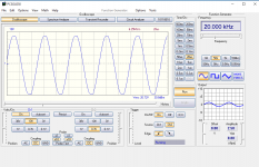
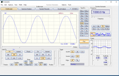
I've had some time to begin testing the VHex+EC. After a couple hiccups in assembly it's up and running beautifully and sounding excellent. It's very stable and the bias drops very slightly as temperature rises. Clipping is nicely rounded at 85W with +/-48V supplies and an 8 ohm dummy load. Here's some initial test results.
Attachments
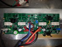
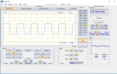
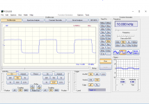
Board look really nice, I especially like how bundled together the cables are. A question regarding the messurements: is it normal that in each one +V and -V aren't of the same value? For example (if I interpret the reading right) in the first pic you have a max of +35V but a min of -40V
Good looking board!
Is there a schematic to accompany this board? Apologies if already posted earlier in the thread.
Is there a schematic to accompany this board? Apologies if already posted earlier in the thread.
Board look really nice, I especially like how bundled together the cables are. A question regarding the messurements: is it normal that in each one +V and -V aren't of the same value? For example (if I interpret the reading right) in the first pic you have a max of +35V but a min of -40V
The zero line isn't centered on the scope screen. Output is + & - 26VRMS at clipping. The scope I use for initial testing is a POS USB scope because it's quick and easy. Proper testing is done on much better equipment.
Good looking board!
Is there a schematic to accompany this board? Apologies if already posted earlier in the thread.
More info is coming. I need to update the schematic with as built values.
The zero line isn't centered on the scope screen. Output is + & - 26VRMS at clipping. The scope I use for initial testing is a POS USB scope because it's quick and easy. Proper testing is done on much better equipment.
Ah, I see. Thanks for explaning.
With all these VHEX+ variants, has anyone considered using Linear Technology's LT1166 to bias the output FETs?
It was designed to bias class AB power FETs and looks like it could drop in place of the MJE340 and LED bias circuit. It measures the voltage across each source resistor to control the bias, so is temperature independent.
Figure 7 of the LT1166 datasheet shows the general idea of using it between current sources from each rail, as in VHEX. Very simple looking. Ignore the op amp in fig 7 and other circuits that require separate power supplies for the chip.
Current Drive + Constant Power
Hi All,
I'm continuing thinking in the direction of combining the principles of current drive in voltage amplification and as-close-as-possible-to-constant-power operation of IPS and VAS stages.
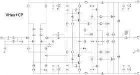
Attached is a new design, based on these principles.
V-to-I convertion in the input LTP, then current scaling with the mirror, then I-to-V conversion by the common-base cascode, loaded by a high-quality CCS.
High linearity and low phase shifts in every stage allow very light, simple compensation - a little bit of shunt at the VAS output (22pF || 2), plus a small lead capacitor (2.2pF) as part of NFB network.
OPS can be built with a single output pair, although I prefer two pairs for safer operation at lower-impedance loads. 100mA of quiescent current per opuput pair is enough.
Clean clipping, good step response, low distortion and excellent harmonics profile are promising delicious sound in a good build.
Cheers,
Valery
Hi All,
I'm continuing thinking in the direction of combining the principles of current drive in voltage amplification and as-close-as-possible-to-constant-power operation of IPS and VAS stages.
Attached is a new design, based on these principles.
V-to-I convertion in the input LTP, then current scaling with the mirror, then I-to-V conversion by the common-base cascode, loaded by a high-quality CCS.
High linearity and low phase shifts in every stage allow very light, simple compensation - a little bit of shunt at the VAS output (22pF || 2), plus a small lead capacitor (2.2pF) as part of NFB network.
OPS can be built with a single output pair, although I prefer two pairs for safer operation at lower-impedance loads. 100mA of quiescent current per opuput pair is enough.
Clean clipping, good step response, low distortion and excellent harmonics profile are promising delicious sound in a good build.
Cheers,
Valery
Attachments
-
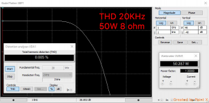 04-Bode-THD-50W.png212.4 KB · Views: 188
 -
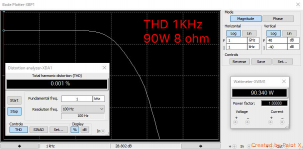 03-Bode-THD-90W.png214.3 KB · Views: 180
 -
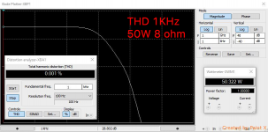 03-Bode-THD-50W.png213.9 KB · Views: 182
 -
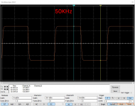 02-SQR-50KHz.png249.6 KB · Views: 191
 -
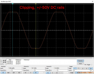 01-Clipping.png305.2 KB · Views: 201
 -
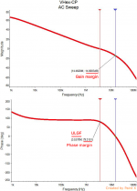 01-AC-Sweep.png227.9 KB · Views: 429
 -
 00-VHex-CP-Sch.jpg361.5 KB · Views: 444
 -
 04-Bode-THD-90W.png217.3 KB · Views: 209
- Home
- Amplifiers
- Solid State
- Sons of VHex