Hi Valery,
Did you compensate the divider for the sound card? I found it was necessary with the card I used.
-Chris
Did you compensate the divider for the sound card? I found it was necessary with the card I used.
-Chris
Hi Valery,
Did you compensate the divider for the sound card? I found it was necessary with the card I used.
-Chris
Hi Chris,
No, I actually didn't, but I will probably look closer at it as soon as my lab will be re-assembled (I have moved from the space I rented for it, so everything is packed at the moment 🙄).
Fans or water cooling. CPU coolers with heat pipes to a pad that is same size as metal tab outline. Mount the MOSFET in a copper block with water impingement jets on backside of thin copper wall separating MOSFET from water flow. The stagnation point flow of water jet had large gradients to remove a lot of heat, fast.
Hi xrk071,
Having intention to duplicate the Sons of VHex and abusing high level bias to make it close to Vzaichenko "philisophy of zero distortion", I wander about thermal resistance of those CPU with a belief that you would help (my zero experiences).
HTML:
http://www.ebay.com/itm/New-Water-cooling-Copper-Water-Block-40-40-10-mm-CPU-GPU-graphics-Chip-/221138494127?hash=item337ce1a2af:g:utYAAOSwanRXhwTlHi xrk071,
Having intention to duplicate the Sons of VHex and abusing high level bias to make it close to Vzaichenko "philisophy of zero distortion", I wander about thermal resistance of those CPU with a belief that you would help (my zero experiences).
Many thanks and warm regardsHTML:http://www.ebay.com/itm/New-Water-cooling-Copper-Water-Block-40-40-10-mm-CPU-GPU-graphics-Chip-/221138494127?hash=item337ce1a2af:g:utYAAOSwanRXhwTl
That's not impingement cooling, but for the levels of heat I think we are talking about, should be fine. Only tricky thing is you can't drill and tap the water cooling block unless it was designed with strategically placed solid bosses for the purpose. So it will have to be either clamped with a few bolts and a a flat bar stock, or a large spring clip for office supplies.

Heat transfer differential between natural convection and forced air is about 10x to 100x depending on air flow rate via fan. Heat transfer difference of going to water vs air is about 1000x. So, the difference between some passive radiator fins and a water cooled copper block with a pump is huge. Think of how many kW or MW an automotive engine puts out - and how effective water cooling is for the car's blocks and cylinder heads. And it's not even made of copper.
For the VHex+ and the VHex-BT, these types of cooling aren't required at all. These amps run very cool even at high output levels on modest heat sinks. Distortion levels make it obvious there is no audible gain to be had by raising the bias current levels, and any sonic improvement will be far negated by adding unnecessary fan/motor noise and reduced reliability over passive cooling. This sort of cooling is for class A or equipment closets.
Agree that VHeX+ runs fine with basic heatsink. I was just answering the hypothetical what if one needed very high heat transfer.
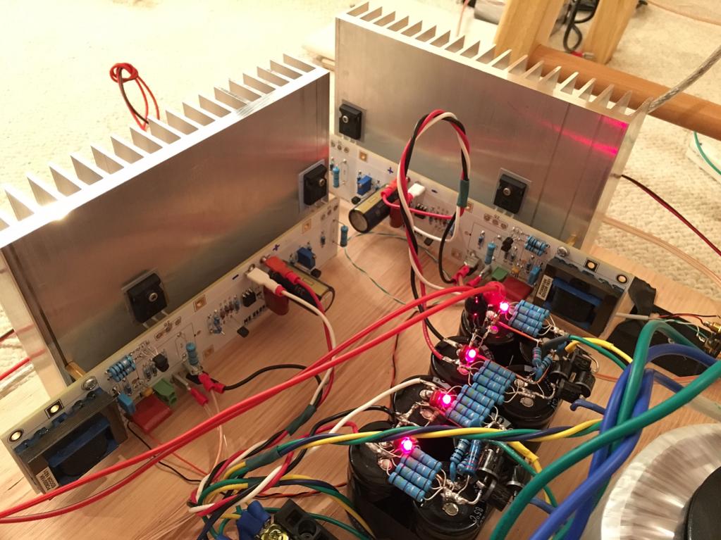
Same heatsink as one on my VHEX+ but double height was not enough for single pair of IRFP240/9240 in class A with 25v rails a la Pass M2. It was amazing to witness such unmitigated amounts of heat from same pair of MOSFETs in pure class A with 1.3amps bias. I had to supplement with small 60mm 12v fan running half speed.
Same heatsink as one on my VHEX+ but double height was not enough for single pair of IRFP240/9240 in class A with 25v rails a la Pass M2. It was amazing to witness such unmitigated amounts of heat from same pair of MOSFETs in pure class A with 1.3amps bias. I had to supplement with small 60mm 12v fan running half speed.
Last edited:
Yes it's quite amazing how much heat Class A produces.
From my listening and measurements I can't say that the heat was worth it. 😛
@xrk971, very impressed with your class A heat sinking photo
@jwilhelm, sorry to not express myself clearer.
My intention is looking for an individual water heat sink so I can mount power fet without BeO or mica insulator. The device is fastened to the copper water jacket by lead free solder.
Each jacket is dissipated heat by water (car radiator fluid) via plastic hoses to create a zero electrical connection.
Cheers
From my listening and measurements I can't say that the heat was worth it. 😛
Same thought here
@xrk971, very impressed with your class A heat sinking photo
@jwilhelm, sorry to not express myself clearer.
My intention is looking for an individual water heat sink so I can mount power fet without BeO or mica insulator. The device is fastened to the copper water jacket by lead free solder.
Each jacket is dissipated heat by water (car radiator fluid) via plastic hoses to create a zero electrical connection.
Cheers
You need to be careful doing this. It adds capacitance to the circuit. This is a grey area weather or not it is an issue. My VTrench doesn't like it.
What does the transformer do?
http://www.diyaudio.com/forums/pass-labs/281520-official-m2-schematic.html
It's an autoformer that provides the 6dB of *passive* gain between input stage and output stage. In the process it adds some nice H3 harmonics 😀
Very elegant and very simple. You can build it in minutes. The bias circuit is also rock stable and worry free.
Unfortunately, the sound, is not for my ears... But many people love it - and there is a nice fan base of folks who say it sounds like a nice SET tube amp but with 25 watts to play with (if you have a line pre-amp as 14dB gain is all it has natively).
You can listen to it compared to 9 other amps here:
http://www.diyaudio.com/forums/soli...audition-very-simple-quasi-mosfet-amp-16.html
Last edited:
Hi MossFed,
You might not want to do that. The heat sink must be connected to an AC ground, or common or the circuit may oscillate big time! Making it all live really creates a high likelihood of short circuits and surprise sparks when poking around doing testing. If you are that close to maximum dissipation, then you're going to run into trouble with normal dust accumulation down the road. You need to design in more thermal head room.
The only okay place I have seen this done is in industrial equipment that employ lockouts so you can't make those errors that would create excessive current flow. I have seen it done in consumer gear (Pioneer, Nakamichi for example), and I have seen technicians blow those up.
What might be more worthwhile is to make certain that your mounting surface is smooth and flat, and the material behind the devices is thick enough to conduct heat efficiently "sideways", to act as a heat spreader.
-Chris
I don't think you are going to lose much with a single layer silicone insulator pad in between the transistor and heatsink. Add some thermal grease if you want as that helps. If you want to live on the edge, try thin sheets of teflon tape (plumbing tape). Wrap layer upon layer until the continuity check does not show conduction anymore. But that should get a very thin layer of insulation. Be careful if cold flow though - tighten it and it squeezes out. Single layer of Kapton tape may also be very good.
You need to be careful doing this. It adds capacitance to the circuit. This is a grey area weather or not it is an issue. My VTrench doesn't like it.
I think the IRFP260 - IRFP9260 that i intended to use is an enhanced MosFet, not VTrench
Talking about adding capacitance, means surface area, distance separation and dielectric constant, the fet flange (drain) to aluminium heatsink has more Farad than the one on water jacket with an inch insulator stand off to chassis.
Cheers
Hi MossFed,
You might not want to do that. The heat sink must be connected to an AC ground, or common or the circuit may oscillate big time!
...
-Chris
Hi Chris
Thanks mate for your advice, each individual water jacket (40mmx40mmx10mm) will be secured with insulator stand off to chassis then RF bypass to ground with 0.001/0,01 uF capacitor in parallel to avoid acting like a microwave antenna.
I don't think you are going to lose much with a single layer silicone insulator pad in between the transistor and heatsink. Add some thermal grease if you want as that helps. If you want to live on the edge, try thin sheets of teflon tape (plumbing tape). Wrap layer upon layer until the continuity check does not show conduction anymore. But that should get a very thin layer of insulation. Be careful if cold flow though - tighten it and it squeezes out. Single layer of Kapton tape may also be very good.
Just want to make my class A as small as possible with respect to thermal dissipation.
Thanks for your Kapton input, will try it.
I think the IRFP260 - IRFP9260 that i intended to use is an enhanced MosFet, not VTrench
Talking about adding capacitance, means surface area, distance separation and dielectric constant, the fet flange (drain) to aluminium heatsink has more Farad than the one on water jacket with an inch insulator stand off to chassis.
Cheers
I was referring to my VTrench amplifier with Trenchfet output devices. When I tried using direct copper connection to the Trenchfet to aid cooling, it became unstable and showed some serious oscillation.
- Home
- Amplifiers
- Solid State
- Sons of VHex