That's right, but an advantage of the bootstrap - it does not "eat" the swing, moreover - you extend the rails with the bootstrap, allowing rail-to-rail operation with no additional lifted rails required.
CCS would provide higher impedance and better overall precision, but it would also limit the swing. Well, in top of the top quality "no compromise" builds I like to use CCSs - no problem to sacrifice some efficiency. But for such a compact, relatively simple thing - bootstrap is an excellent solution.
One interesting observation - it exploded my brain before I understood what was going on. Those bootstrap caps really don't like to be heated up. When they were placed close to the hot 1W resistors, after some time I had some short "dry" clicks in the speakers from time to time. As I realized over the time, they were caused by some processes in the hot electrolytics. Now the caps are lifted about 10mm above the board and placed a little bit away from the hot parts - the clicks are gone since then. The amp is dead silent - I really can't say if it's on or off, touching the speakers with my ear. It's not even silence - it's nothing 😀
As Albert Einstein said long time ago: "The only source of knowledge is experience. All the rest is just information." 😉
I've had the same noise observation with the whole VHex series, and the NS-OPS series of amplifiers. They give you no sensation of even being on, until the music begins to play.
Are C20 and C21 okay with a 100V rating? They must be seeing very close to double rail voltage at full output.
Are C20 and C21 okay with a 100V rating? They must be seeing very close to double rail voltage at full output.
In normal operation they see only about half-a-rail and this voltage stays constant at any swing - that's the feature of the bootstrap.
The voltage will start growing in case of some trouble, if the output stays statically close to one of the rails, for example. But then protection will switch the amp off.
Last edited:
Hi Valery
That's interesting about the caps. I always try to keep electros away from heat source that is dissipating more than about 100mW as every 10C increase in ambient temp is said to halve the life of the cap!
I should think that at full power, the bootstrap cap can see up to 1/2 Vrail + Vp in the opposite direction, assuming the divider resistors around the bootstrap cap are of equal value, as is the case with this design of yours.
So if the amp was running on 35V rails and could hit 32Vp on clip onset then the cap might see up to 49.5V. In that example I would use 50V rated decoupling caps in the power supply and a 63V one for the bootstrap.
Ummm...
Why "+ Vp in the opposite direction"?
The bootstrap cap sees 1/2 Vrail and this voltage is virtually constant, regardless of the amplitude of the output signal. It's the same at idle or at the full swing.
That's the way dynamic load for the drivers is working, the reason why dinamic impedance of the drivers' load is much higher than the static one.
The way it looks to me, the positive side of C20 is on a voltage divider which would limit it's voltage to a minimum of half rail voltage. The negative side is connected to output which will swing close to negative rail on full output. How does it only see half rail voltage total?(Not disagreeing with you, just trying to figure out how it works)
How the bootstrap works
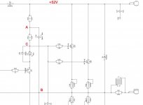
OK, here is how it works - see the fragment of the schematic.
Point B is the output. With no signal its potential is 0.
Point C is our bias. Referenced to B its around 4V.
The most interesting - point A. With no signal its potential = (52V - 4V) / 2 + 4V = 28V.
So, the bootstrap capacitor, C20, sees 28V.
Now the magic starts. With signal, because C20 always tries to keep the potential it's charged to, point A follows point B very closely, keeping the voltage drop over C20 CONSTANT. This is the key to the whole thing.
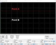
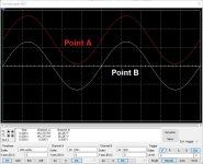
See the curves (static and dynamic). Red - point A, white - point B.
What it gives us - basically 2 key things:
1) Point A can easily go above the rails. Meaning, we can have rail-to-rail output swing without the need of additional lifted-rails PSU for the front-end.
2) The driver's (Q11) dynamic load impedance is very high - the bootstrap circuit behaves as CCS. Q11's idle current = (28V - 4V) / 2K2 = 10.9mA.
As we have seen above, this voltage (28V - 4V) stays virtually constant at any swing.
So, current through Q11 also stays virtually constant at any swing. That means, despite the fact, static load of Q11 = 4K4, dynamic one is MUCH higher. With signal Q11 sees much higher value, than 4K4. Same thing, as if there would be a CCS here - well, not that close to "ideal", but still.
In the ideal world:
Dynamic load impedance = (delta V / delta I) at the emitter of Q11.
Delta I = zero (as voltage over R33 is virtually constant, "I" does not change).
Dynamic load impedance = (delta V / zero) = infinity, regardless of delta V.
In reality, delta I slightly differs from zero, so it's not exactly infinity, but stays rather high. My simulation is showing the load value = around 61K @ 1KHz there. At 10.9mA standing current - more than enough.
So. One capacitor - C20 - does fantastic things here. Consider it as dynamic level shifter. Same thing - C21 in the negative shoulder.
OK, here is how it works - see the fragment of the schematic.
Point B is the output. With no signal its potential is 0.
Point C is our bias. Referenced to B its around 4V.
The most interesting - point A. With no signal its potential = (52V - 4V) / 2 + 4V = 28V.
So, the bootstrap capacitor, C20, sees 28V.
Now the magic starts. With signal, because C20 always tries to keep the potential it's charged to, point A follows point B very closely, keeping the voltage drop over C20 CONSTANT. This is the key to the whole thing.
See the curves (static and dynamic). Red - point A, white - point B.
What it gives us - basically 2 key things:
1) Point A can easily go above the rails. Meaning, we can have rail-to-rail output swing without the need of additional lifted-rails PSU for the front-end.
2) The driver's (Q11) dynamic load impedance is very high - the bootstrap circuit behaves as CCS. Q11's idle current = (28V - 4V) / 2K2 = 10.9mA.
As we have seen above, this voltage (28V - 4V) stays virtually constant at any swing.
So, current through Q11 also stays virtually constant at any swing. That means, despite the fact, static load of Q11 = 4K4, dynamic one is MUCH higher. With signal Q11 sees much higher value, than 4K4. Same thing, as if there would be a CCS here - well, not that close to "ideal", but still.
In the ideal world:
Dynamic load impedance = (delta V / delta I) at the emitter of Q11.
Delta I = zero (as voltage over R33 is virtually constant, "I" does not change).
Dynamic load impedance = (delta V / zero) = infinity, regardless of delta V.
In reality, delta I slightly differs from zero, so it's not exactly infinity, but stays rather high. My simulation is showing the load value = around 61K @ 1KHz there. At 10.9mA standing current - more than enough.
So. One capacitor - C20 - does fantastic things here. Consider it as dynamic level shifter. Same thing - C21 in the negative shoulder.
Attachments
Valery,
Thanks for that nice detailed explanation of bootstrap operation.
I have always wondered how that worked.

Thanks for that nice detailed explanation of bootstrap operation.
I have always wondered how that worked.
HexFET+BT mid term test
I ran the new HexFET+BT almost constantly during 3 days with different music material at moderate / high listening volumes.
Runs very smoothly, relatively cool. Very pleasant listening. Punchy bass, airy highs. Very easy-going. My speakers definitely like it 😀
Jwilhelm will have the boards available in the nearest days - the order is already placed
Congratulations, Valery, this is a very good amp, I love the folded cascade VAS. Very fast, and the compensation at the input stage is very clever too.
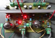
I have designed an amp with 62V rails, 125mA quiescent, monster mosfets and large heatsinks. Here is a picture of one channel from the side, it's 350x100, 0.28C/watt, and very beefy. It hardly gets warm, although a 4R load frightens a bit.......
Cheers,
Hugh
I have designed an amp with 62V rails, 125mA quiescent, monster mosfets and large heatsinks. Here is a picture of one channel from the side, it's 350x100, 0.28C/watt, and very beefy. It hardly gets warm, although a 4R load frightens a bit.......
Cheers,
Hugh
Attachments

Thank you Hugh!
Yes, I'm also thinking about the bridged amp with monster FETs 😎
Jeff is testing some better ways to remove the heat from them as efficiently as possible now. This is the main power-limiting factor now - I mean, we are perfectly within the SOA in terms of the maximum voltage and current - and even the maximum power! - but then it's really not easy to remove that much heat from those devices. Experimenting with machined copper pads 🙄
Cheers,
Valery
Fans or water cooling. CPU coolers with heat pipes to a pad that is same size as metal tab outline. Mount the MOSFET in a copper block with water impingement jets on backside of thin copper wall separating MOSFET from water flow. The stagnation point flow of water jet had large gradients to remove a lot of heat, fast.
I'm going to try to stay with passive cooling methods for the VTrench. I've had it reliably running at 250W RMS output with the output devices operating at 195F on a 50lb block of aluminum. I tried 2 ohm loading on 63V rails unsuccessfully, and am in the midst of trying to get another channel operating. I've got copper heat spreaders machined and ready to test.
TubieHex
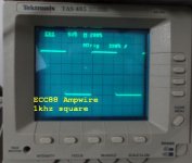
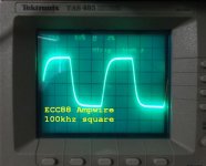
Guys, we kind of forgot about the excellent version of VHex's front-end with 6DJ8 / ECC88 tube at the input.
It's been tested by Terry in December 2015 (called AmpliWire/Tubie at that time) in combination with the miniSlew OPS - see his post here (I'm just re-posting some of his pictures):
Tubie test with miniSlew
There is also a good front-end layout, designed by Marc (Idefixes) here:
Tubie front-end layout
Attached is the full schematic, including the Tubie front-end and VHex OPS.
Current drive with the tube at the input + HexFet OPS - this is going to be a coolest amp.
The layout needs to be updated, incorporating the whole thing though...
Attachments


Very nice Valery. I actually have some tubes on hand but so many amp projects in the queue already.
Could some 2SK170's be used in a similar manner for the input stage here?
Could some 2SK170's be used in a similar manner for the input stage here?
Very nice Valery. I actually have some tubes on hand but so many amp projects in the queue already.
Could some 2SK170's be used in a similar manner for the input stage here?
2SK170's - possible in principle, need to run a few tests.
- Home
- Amplifiers
- Solid State
- Sons of VHex