Hi again!
Got my sick little 4 year kid next to me on the other computer. He´s playing Battlefield2 and other "great" kids-stuff (at the moment he running a gocart through a garden with Green Day on high volume) and I´ve been running through all of the comments in this tread and a few more today.
THe final question: Your Mr Mardis mods seems to be the one. But a "stiffener cap" seems to be something to add on - but again... there are a few different ways to do this if You still vant Your led to lit ore not etc. Any suggestions?
Abut case/enclosures, look att this site. Looks great: http://www.autocostruire.com
Todays result so far: Two pages of notes of "everything" I´ve need to know and think about......
This seems to be a good place to find components for a Suede as Elfa ande the rest of the Swedish vendors doesn´t seem to have that much of the needed components: http://www.world-designs.co.uk/
Is it good?
hakan.hargedahl said:
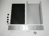
What about this?
300mm x 195mm x 60mm (approx.)
Attachments

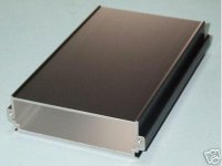
I've also found some of these on eBay - but it is cheaper going diectly to the seller. They are not as nice as the prefessional looking one above and don't come with end plates - but they are still very neat and perfect if you want to make your own ends (maybe from some nice wood or something else appealing). They are also a lot smaller - 160mm x 100mm x 25mm (approx).
Attachments
Nice looking Cases. But what I'll do is that I´ll order one of the cases from Autocostruiture just to see if there are something for us DIYers here.
Have also put Audio1st and Mr M Mardis pictures on the same page including difference's nad question about what those have on the sound, trying to getting closer to the definition of some kind of "extended-Stealth". Will convert my picture from ppt to Jpg (ore something else) as soon as I find out how.
Have also put Audio1st and Mr M Mardis pictures on the same page including difference's nad question about what those have on the sound, trying to getting closer to the definition of some kind of "extended-Stealth". Will convert my picture from ppt to Jpg (ore something else) as soon as I find out how.
hakan.hargedahl said:[B. Will convert my picture from ppt to Jpg -- as soon as I find out how. [/B]
Go to File/Save As and choose the format you want from the drop down list. In your case choose jpg. PowerPoint will ask you is you want to save all slides or just the current one. Make your choice. That's all there is to it!
Pano - former "King of PowerPoint."
Michael. you very kindly used my "Supersonic" T-Amp pic in your gallery. I have been meaning to suggest to you that you include in the "Wiki" the mod to make the T-Amp into a power amp, thereby doing away with the pot altogether. There is also a shunt mode pot tweak that can be done a la Clari T amp. If you would like me to post the drawings for these mods I will do so.
Rob.
Rob.
Hi Puffin
I am very much interested in the shunt tweak, which I have been reading about elsewhere on this forum. Your drawings would be most welcome, so please post 😎 . Hopefully it can be used also with an Amp6.
Thank you
berthej
I am very much interested in the shunt tweak, which I have been reading about elsewhere on this forum. Your drawings would be most welcome, so please post 😎 . Hopefully it can be used also with an Amp6.
Thank you
berthej
Hi Puffin,
good idea, I'll get to work on it this week.
I'm not a fan of the shunt mode pot, but I know a lot of people like it.
good idea, I'll get to work on it this week.
I'm not a fan of the shunt mode pot, but I know a lot of people like it.

Oh...erh.. it's an AMP32 from the link below (not affiliated, only love the amps and like the owner...)
Hey Sharky the Frog,
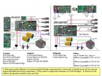
Those mods are pretty much the same. Both diagrams are by Audio 1st, because he does such nice ones.
Going in via the stock wires is easier for most people. Going right to the PCB, as shown on the left, is probably better.
The diagram on the right does not show a replacement tank cap, but it would certainly be part of the mod. So they are more or less the same thing.
Thanks for Your comments MM.
Working as a Business Operations Developer on an Insurance Company in Sweden looking for "the best result with minimum input" is a backbone reaction. So is "risk minimazing" ;-)
Did find a number of common mods and a few differencies with the two drawing that You and Audio1st had done.
Lets say that the change of C10 to 680-1500 uF is one of the "standardmods". Connecting to the stock wires would be easier for guys like me, fine, taken.
1) Audio1st remove L01/L02 and has input resistors, and You still have output caps, which he doesn't. What difference would those differenies make to the actual sound?
2) Any ideas about connecting "stiffener caps"?
Maybe we can the two drawings together in one "final" (maybe also with the latest topic - Shunt tweak as an option).
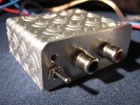
I have found a good place for stiffener caps is at the chip end of the board.
If you use the through-hole intended for the return of the power switch for the positive, and attach the negative lead to the solder-covered ground plane that surrounds the chip, it's a pretty secure connection, and gets you very close to the chip. I have a 4700 Nichicon connected this way, and it lays down very nicely right beside the board.
Power can be connected to the other switch hole/pad, provided the two switch pads are connected. This bypasses the long thin trace from the DC jack at the other end of the board. If you do this, be aware that this trace you're bypassing can act like a fuse if you hook up the PS with incorrect polarity. So if you bypass it, you're loosing this protection.
--Buckapound
Great, Buckapound!
Will put a stiffener cap at the end exactly as You describe it. Sounds simple and reliable.
Do I understand You right that:
1) You remove the powerswitch and connect the two pads (having the switch on the PS instead?!)?
2) You say that the thin trace under the board is so thin that it accually can act as a fuse?
Both my boards/amps are still in original shape and place and used by my two sons who don't want them removed until I'm kind of shore of what to do and with all the necessary parts on site, so I still have to (like to) rely on the great pictures in this thread instead of toring them out of their cases to be looked at.
1) You remove the powerswitch and connect the two pads (having the switch on the PS instead?!)?
Yes, you can actually snake the capacitor lead down thru the switch hole nearest the chip, bend it into a "U," then the back up through the other switch hole, leaving just enough wire sticking up that you can attach a wire to it that will go first to a switch, and then to the power supply (or some other arangement to turn off & on).
2) You say that the thin trace under the board is so thin that it accually can act as a fuse?
Yes, when I hooked up the PS backward, the trace smoked, but it saved the chip and everything else. Not a great endorsement for how much power it carried, so it seemed like going into the return pad from the original switch would be a much better connection--pretty close to the chip, too. But of course, you lose the "fuse" quality of the thin trace.
--Buckapound
Thanks again Buckapound!
Getting closer . . . . but isn't it funny. When You think You are there You realise Your not.
Jumped into a Thread about Input caps - have som spare time at my jobs as a change. The "priced" Black Gates where not recommended, but in different ways Audicaps, Sonicaps (by some), Auricaps, Obbligatos as well as Solem..... Great, cleared things up for a Newbi. ;-)
Planning on making my "operation" on my two T-amps during christmas holiday. After that I think I do some kind of drawing/schematic about my operation, which will be some sort of extended Stealth - as a "gift" to or starting point for other Newbies. And as a way of letting You all guys (MM, Buckapound, Audio1st and all the rest of You great guys I just forgot the names of) not getting to much basic questions from us Newbies.
Just waiting for some answers on the questions on my prewious comparing drawing.
Finaly!
Did order my mod-pieces Yesterday. A little bit this and a little bit of that from two differerent Swedish ditributors
Mundorf Mcaps 2,2uF for the input signal, á 4€
Vishay low ESR 470 uF (couldn´t find any 680s) for C10 replacm, á 1€
Jinghai Ultra low ESR 5600cF (maybe two on each) for stiffening caps, á 2€
Wima MK2 0,15uF for output signal caps
0,25W 1% resistors for input signal
and all the rest except for the speaker terminals which I couldn´t find any descent small ones, still looking.
So now I just have to wait and se what comes out of this....
Warming up to soldermaniackholiday....
- Status
- Not open for further replies.
- Home
- Amplifiers
- Class D
- Sonic Impact 5066 Parts List & Modifications