Well this is what I could find here up north, so be it.... ;-)
As for the pricing (Us$70 for a T-amp) the marked for "specials" in whatever area is not he best.
Thanks to the net paypal etc tinhgs are getting lighter and lighter - as well as the sun that will start to stay up more and more again at the 22th of dec.
I´ll be back....
As for the pricing (Us$70 for a T-amp) the marked for "specials" in whatever area is not he best.
Thanks to the net paypal etc tinhgs are getting lighter and lighter - as well as the sun that will start to stay up more and more again at the 22th of dec.
I´ll be back....
Halftime!
Got rid of the battery compartments and lots of space apeard. I´m mounting the board 90degr turned with the stiffener cap at the end. The two inpt caps wll be put one in the end of each batt comp. Fits perfect.
Got everything soldered except for the Allps pot that hasn´t arrived yet. Hope it will fit together with the rest of the stuff.
Got in to bit trouble thou. After I got rid of the R01, R01, C3 and C4 I couldn´t bridge on the place for the C3. Nothing is accepted to attach to the place where the C3 was. Big trouble . Have no idea if I could do anything to get the solder pewter to attach.
The next step is to find some other place to bridge to. Have found the L1 and R1 but are not really shure about where the right side of them are to attach to each other. Especially as they are on the opposit side of the board.
Almost here but apparantly not . . . .but so far Happy anyway.....
Got rid of the battery compartments and lots of space apeard. I´m mounting the board 90degr turned with the stiffener cap at the end. The two inpt caps wll be put one in the end of each batt comp. Fits perfect.
Got everything soldered except for the Allps pot that hasn´t arrived yet. Hope it will fit together with the rest of the stuff.
Got in to bit trouble thou. After I got rid of the R01, R01, C3 and C4 I couldn´t bridge on the place for the C3. Nothing is accepted to attach to the place where the C3 was. Big trouble
. Have no idea if I could do anything to get the solder pewter to attach. The next step is to find some other place to bridge to. Have found the L1 and R1 but are not really shure about where the right side of them are to attach to each other. Especially as they are on the opposit side of the board.
Almost here but apparantly not . . . .but so far Happy anyway.....
Yes, bridging those tiny pads is hard.
I have been trying to simply place a fine wire in parallel with the capacitors, effectively bypassing them.
If you do happen to remove the caps, take a very fine single strand of wire from a piece of multi strand wire. Hold it in position with a clip or something. Place a tiny dab of solder on the tip of your soldering iron, and just touch it to the place where the wire and pad meet, then pull up. It should have formed a bond. Repeat with the other pad. Don't hold the soldering iron on for more than a moment. If it doesn't stick, try again.
Additional flux, either on the joint or right on the tip of the iron, makes this easier.
It may be helpful to leave the wire long and use the extended ends to hold in position with tape or some kind of a clip. Once soldered, trim off the extra wire with a sharp knife.
-Buckapound
Thanks once again Buckapound for Yor patience with me!
Ok, I´ll give it a try. Flux... aaa that´s something I remeber from 25 years ago. I didn´t think that was still around - that this was something that was used just because it wasn´t in the solder at that time - but is nowdays. I´ll try to find some at the store tomorrow.
I tried to rub the little places for the C3 with a screwdriver because I thought that it might had come some rubbish from the board on the spots - but I don´t know if that is possible? Anyway it didn´t make any differense.
We´ll se what tomorrow has in mind for me - maybe a nice bridge on C3 and some Allps arriving...
I´ll attach a pic of "half way thrue" as soon as I find out a way of make them not bigger than 1Mb... Another trial as none of my picture programs seems to have that facility...
/H
Sharkythefrog said:as soon as I find out a way of make them not bigger than 1Mb... Another trial as none of my picture programs seems to have that facility...
Whaaaat? How can that be?
Just resize your photo to 800x600 or 640x480 (crop first, if you need to) then save as a medium quality jpeg. (.jpg)
There are tons of programs out there that will do it. For a free and easy, fast image viewer for WIndoze, try "SlowView". It's been discontinued but you can still find it for download. I use it and love it, opens super fast.
Try M$ Paint.
right click the pic and chose open with Paint... go to Image - Stretch/Skew - change from 100% to 50% on both vertical and horizontal.
You ma have to do this a few times - for example, I have a 3 Megapixel camera, so I first stretch 50% both horizontal/vertical and then again at 75% horiozontal/vertical.
And save as a jpeg too. will get you nice and perfect. Don't waste your money on software - you have it already....
Finally!
Used Your recipie for fewer pixels, worked great. Newbie in many areas You see...
Halfway through I think I got the bridge over C3 right where it should. And if it´s not I have found a way to bridge from the side of C3 that is easier to solder to and to the right end of R1 as a life line.
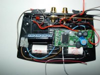
Attach my construction in the half way stage. Using the two holes with plastic bolts and nuts to fix the board. The three wires on the top (red, black and brown) are going to the pot. So is the white and red on the bottom, as well as the loose ends of the resistors. The white ones on the bottom are going to the red Led as loosened from the board and will put back in the original position in the case. The case will look as original except for a new knob on the allps pot.
Not the nicest wiring seen on the net but . . . .
The allps has arrived so I´ll pick them up tomorrow and se if I have damaged anything or if there will be sound... 🙂
/H
Used Your recipie for fewer pixels, worked great. Newbie in many areas You see...
Halfway through I think I got the bridge over C3 right where it should. And if it´s not I have found a way to bridge from the side of C3 that is easier to solder to and to the right end of R1 as a life line.
Attach my construction in the half way stage. Using the two holes with plastic bolts and nuts to fix the board. The three wires on the top (red, black and brown) are going to the pot. So is the white and red on the bottom, as well as the loose ends of the resistors. The white ones on the bottom are going to the red Led as loosened from the board and will put back in the original position in the case. The case will look as original except for a new knob on the allps pot.
Not the nicest wiring seen on the net but . . . .
The allps has arrived so I´ll pick them up tomorrow and se if I have damaged anything or if there will be sound... 🙂
/H
Attachments
Sharkythefrog said:Halftime!
....
Got in to bit trouble thou. After I got rid of the R01, R01, C3 and C4 I couldn´t bridge on the place for the C3. Nothing is accepted to attach to the place where the C3 was. Big trouble
Yes, the Buckapound’s suggestion is very helpful. About SMD, take a look also to the “41hz” suggestion about SMD components soldering that it could appropriate to this situation (especially the paragraph "And now to the actual work" in the start of the topic)
http://www.41hz.com/Forums/topic.asp?TOPIC_ID=21
Contrariwise Buckapound, I had used a piece of solid core wire, I think It’s more simply to solder... look at "c4"in the second image in this my page
http://it.geocities.com/silvio_b2002/audio/t-amp/surgery.htm
My "t-amp site" http://it.geocities.com/silvio_b2002/index.htm
OT: ...I am thinking to your sunset "in stop" ... wonderfullllllll!
Silvio
Could someone recommend a suitable 10000 uF stiffening cap sold at digikey please?
Also what is the purpose of replacing R6, R5 with a 20K? Those reisitors in the 0603 size are kinda pricey!
Also what is the purpose of replacing R6, R5 with a 20K? Those reisitors in the 0603 size are kinda pricey!
help modders
hi everyone,
I recently finished the stealth mod, seemed fine until i realised I wasn't listening in stereo, thru a test cd, both channels play the same things. Also there seems to be a slight hum that fades when you turn up the volume all the way.
thanks
hernan
hi everyone,
I recently finished the stealth mod, seemed fine until i realised I wasn't listening in stereo, thru a test cd, both channels play the same things. Also there seems to be a slight hum that fades when you turn up the volume all the way.
thanks
hernan
Congratulation Herpaw!!!
At least You got some sound.
I did finish my Extended-Stealth a few days ago and there were . . . no sound what so ever - even the red led is dead. At the same time my multimeter broke down so I have no idea of what is broken. Actually I´m not sure that I would have known that even if I have had a working multi meter as I had my last electronics class in 1976.... 🙂 Probably something got to much heated when I made my first solderings in decades.
Strange to have the same channel in both speakers - did You change ground with a channel?
Silvio Brasini, I will take a look at those pages - even if it seems that I hve bigger problems than that.....
New year new challenges...
Don't worry Sharky....no light is probably a lot better than power and still no sound! 😉Sharkythefrog said:Congratulation Herpaw!!!
At least You got some sound.
I did finish my Extended-Stealth a few days ago and there were . . . no sound what so ever - even the red led is dead. At the same time my multimeter broke down so I have no idea of what is broken. Actually I´m not sure that I would have known that even if I have had a working multi meter as I had my last electronics class in 1976.... 🙂 Probably something got to much heated when I made my first solderings in decades.
Strange to have the same channel in both speakers - did You change ground with a channel?
Silvio Brasini, I will take a look at those pages - even if it seems that I hve bigger problems than that.....
New year new challenges...
If you have no LED then it's a pretty good bet that the power connections are suspect, re-solder and check for trace breaks.....
hi sharky, thanks for your reply,
the thing is a total nightmare to solder, I practised with a broken cellphone before going to T.
well I detected the problem. I kept the volume control with the board and soldered the cables on top, on the other side of the pin connectors. Somehow some solder got stuck between the pins of theL and R channels!!!! I was going awwwllll...... . so i connected it without vol. control, used the cd player volume as a pre, and i was hearing stereo again. Now i got rid of the board but the volume control was not unharmed in the process. Now i need a new volume control.
good luck sharky!!!
hernan
Herpaw - good for You finding your problem. And the sound is...?
Did Your pot brake of the soldering You did???
Lostcause - Thanks for the cheering - No led could be good...., didn´t think of it that way, but You could absolutely be right and if so it´s a minor problem. Will go on with it as soon the kids turn over to their mum, so friday night is saved for having things to do.
hi sharky,
no, no. the pot was damaged while i removed it ( it was glued with epoxy from the inside)to the wooden case I made,and while i got rid of the PCB board. It got disassembled.
the sound is excellent, voices in particular, very clear. The Mod does work indeed. But the sound(as expected) is much much better without the volume control!!. So getting rid of the stock one was a very good recommendation. As i don´t have a pre I will try to use the sub input of a tascam 4 track as one and let the T run as ""power" amp".
Attachments
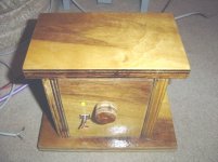
herpaw, glad to hear about the sound.
I do really like the case You´ve made. A few months ago a found a post that had a link to a site where there where dossens of pictures of different T-amp cases. Just lowe it but lost the ink somewhere. If You don´t have to much to do some day try to find it, it´s worth while.
I´ve still not yet got myself a new multimeter and (currage to) getting into a focused error handling of my dedmod (maybe a new brand name) Extended-stealth. I just pass it by on my desk just outside my bedroom a number of times a day - glancing to it thinking "get well You ¤%#¤%".
I make a shot to it during this weekend without work and kids.
If You can wait for a while I have a test with two diffrerent pots. One Alps and one other (a no name brand 1/4 the price coal pot that were "very good for hifi.." according to the vendor), to see what differense there might be as the Alps are hyped everywhere.
PS. Go to the link about the possible dead of the T-amp: http://www.diyaudio.com/forums/showthread.php?s=&threadid=93149
which look pretty sad for us getting to the diy arena.
I´ve still not yet got myself a new multimeter and (currage to) getting into a focused error handling of my dedmod
I'm sincerely hoping I don't end up with one of these! Just starting to attempt the stealth mod by practising on my DOA T-amp - I can flick off the R01 and R02 OK but bridging C3 and 4 is causing me more grief as I seem to be lifting them even with very quick contact with the iron tip. I have had better luck bridging with a tiny loop of wire across the cap. In fact I did manage one loop bridge on my "live" T-amp, but then I wasn't sure it was OK so like a total pratt I switched it on. The left speaker didn't like that

If it's quiet at work I should have it done tomorrow.
Bought me a new multimeter friday in a little electron shop. Gained currage enough to start working with it yesterday, and it was broken from the start, no sign of life. Tryed to shift it today, no other ex at home at the shop, new ones on thursday.....
What can I say
What can I say
Bad luck...
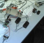
I got mine going OK - people at work are somewhat bemused about the tangle of wires across my desk. I'm using Soniq Sax 2.2uF caps on the input (from http://www.world-designs.co.uk/acatalog/Capacitors.html) - only because I couldn't seem to find a UK source for the Blackgates etc that are usually mentioned..
I haven't been able to pump much volume through yet so I'll have to reserve ultimate judgement until I've got the case ready and got it home.
Attachments
Great for You . . . . Haha!
Interesting mess on Your desk - with the obligory Audio1st drawing on it. No "stiffening caps"??
Like to hear Your "vote" later on. What´s the rest of the system.
Interesting mess on Your desk - with the obligory Audio1st drawing on it. No "stiffening caps"??
Like to hear Your "vote" later on. What´s the rest of the system.
- Status
- Not open for further replies.
- Home
- Amplifiers
- Class D
- Sonic Impact 5066 Parts List & Modifications