OS,
I just asked because I do cad design in Solidworks and just wondered why it was done this way. I know there is a circuit layout section in Solidworks but I have never played with that. I understand there are conventions and rules that you follow and just wondered why things still looked like tape layout. Sort of like me getting back on my old drafting table. I still have mine!
I just asked because I do cad design in Solidworks and just wondered why it was done this way. I know there is a circuit layout section in Solidworks but I have never played with that. I understand there are conventions and rules that you follow and just wondered why things still looked like tape layout. Sort of like me getting back on my old drafting table. I still have mine!
Creepage ...
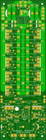
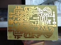
We MIGHT see 150+ V signals on the driver output rails ...
The ground pads of the output collector capacitors are real close
to the driver "signal rails" (traces).
I know this is an amplifier output , and not a UL listed AC appliance ...
but just move those 10 capacitors back a tad closer(1mm) to the main
output pads.
OS
Last edited:
OS,
I just asked because I do cad design in Solidworks and just wondered why it was done this way. I know there is a circuit layout section in Solidworks but I have never played with that. I understand there are conventions and rules that you follow and just wondered why things still looked like tape layout. Sort of like me getting back on my old drafting table. I still have mine!
Most PC MB's also use compounded angles at corners .. it's just how the CAD
works.
I did tape/photo .. too. There , the tape was flexible .. and it was
easier just to bend at a corner. 🙂
OS
We MIGHT see 150+ V signals on the driver output rails ...
The ground pads of the output collector capacitors are real close
to the driver "signal rails" (traces).
I know this is an amplifier output , and not a UL listed AC appliance ...
but just move those 10 capacitors back a tad closer(1mm) to the main
output pads.
OS
Ok, I can push those a little to gain some clearance. Anything else? I think it is getting really close now.
OS,
I may just have to look at UL rating this amplifier for my application, that would be nice if there are no problems in that regard. At the same time I know I won't be running the max voltage that you are planning so I feel confident that you will get it right.
I may just have to look at UL rating this amplifier for my application, that would be nice if there are no problems in that regard. At the same time I know I won't be running the max voltage that you are planning so I feel confident that you will get it right.
Ok, I can push those a little to gain some clearance. Anything else? I think it is getting really close now.
After that ... creepage.com says you could be UL listed !
Perfection !
OS
Are we there yet?
OK, a few more for your viewing pleasure. Hopefully this is getting down the 'fine strokes'.
EDIT: Aw, crap. I remember you saying to remove or reduce the 'rail augmentation pads'.
OK, a few more for your viewing pleasure. Hopefully this is getting down the 'fine strokes'.
EDIT: Aw, crap. I remember you saying to remove or reduce the 'rail augmentation pads'.
Attachments
Last edited:
OK, a few more for your viewing pleasure. Hopefully this is getting down the 'fine strokes'.
1.25mm (creepage), that will get you nearly US outlet voltage (RMS) ..
Overkill ... 😎
OS
Last edited:
1.25mm (creepage), that will get you nearly US outlet voltage (RMS) ..
Overkill ... 😎
OS
Does that mean we have arrived at 'OS Approved' status?
PS - I just noticed .. make top pads look like bottom pads ... F12 should do that.
I use V5.0 , do you use V6.0 ??
OS
I use V5.0 , do you use V6.0 ??
OS
PS - I just noticed .. make top pads look like bottom pads ... F12 should do that.
I use V5.0 , do you use V6.0 ??
OS
ALL of the pads are PTH (F12 applied), do you see something? I just sent the latest to mfg since I believe I caught them before they started. Please say 'good to go'...
Oh, v5 is my version.
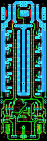
Good to go .. forgive me , you were showing the layout in transparent mode.
That confused me , I usually look (proof) in photoview (xray) .. both sides.
OS
That confused me , I usually look (proof) in photoview (xray) .. both sides.
OS
I make 5 pair OPS now and found 470uF/100V have different pitch (7,5mm) than 470uF/63V (5mm). I must add holes on my PCB. Please use multiple pitch on 470uF cap.
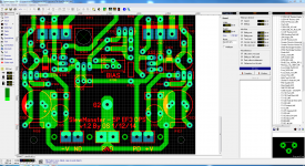
Multi-pitch @ Capacitance Multiplier...
Like this for C103 / C106?
I make 5 pair OPS now and found 470uF/100V have different pitch (7,5mm) than 470uF/63V (5mm). I must add holes on my PCB. Please use multiple pitch on 470uF cap.
Like this for C103 / C106?
Attachments
I made the multi-pitch change suggested by bimo and added text to mark the NFB point (the pad was always there but the text on the silk was over looked previously). I don't think there could be too many more 'tweaks' required. If something genuinely important is noticed, bring it forward please.
At this point are we ready to consider the SlewMonster 5P OPS artwork complete and 'locked-down'? I'll leave the question open for a while before blowing my wad and posting a new set of manufacturing files. I'll check in this evening and if all is a 'go' I'll put up the files.
At this point are we ready to consider the SlewMonster 5P OPS artwork complete and 'locked-down'? I'll leave the question open for a while before blowing my wad and posting a new set of manufacturing files. I'll check in this evening and if all is a 'go' I'll put up the files.
Cool! My board house is waiting in the starting blocks. 😉
I'm thinking I may build the Symasui first.
I'm thinking I may build the Symasui first.
Hi OS and all,
is it possible to have 6 pairs of output because my power amp will have 2 heatsinks by side? Thank You! Maxpou
is it possible to have 6 pairs of output because my power amp will have 2 heatsinks by side? Thank You! Maxpou
Like this for C103 / C106?
Also , the OP collector caps I told you to re-position.Do Multi-pitch for
3.5mm/5mm. some Panasonic's are 3.5mm - most wima's are 5mm PCM.
One can use 2.2u to 22u /63-100v (EL or poly)- many options.
OS
Also , the OP collector caps I told you to re-position.Do Multi-pitch for
3.5mm/5mm. some Panasonic's are 3.5mm - most wima's are 5mm PCM.
One can use 2.2u to 22u /63-100v (EL or poly)- many options.
OS
The OP caps were repositioned. If I move them any closer to the OP then there is no clearance to the base pad. As it sits now there's equal clearance between the OP cap pads and the base pads and driver rail. I'll add back the OP multi pitch, I only took it out becaise the drillings were VERY close. I could specify smaller drillings but we want to keep to just a few sizes ideally. I'll do these later and do more show and tell.
- Home
- Amplifiers
- Solid State
- Slewmaster - CFA vs. VFA "Rumble"