I like having the through hole pads. Since I am one who seems to always end up replacing something, I have learned a way that puts a little less stress on the pads. I cut off the device so all that is left in the hole is the wire. I then heat the solder and as soon as the wire shows movement I lift it out with pinchers. Then I just use my solder pump to remove the solder. I find that the through hole with pads top and bottom survive changes better. My preference would be for all holes to be that way.
Blessings, Terry
Blessings, Terry
OS,
Were you saying yesterday that the Leach and the NAD were the two input sections that had the best distortion response to your full voltage testing from the lowest frequencies to the upper frequencies? I assume that you prefer the Spooky as the best overall design of all the ips sections.
Were you saying yesterday that the Leach and the NAD were the two input sections that had the best distortion response to your full voltage testing from the lowest frequencies to the upper frequencies? I assume that you prefer the Spooky as the best overall design of all the ips sections.
Yes .. Leach/NAD are the VFA/CFA champs.
But the sym has the best performance /simplicity ratio ...
A very common topology among the OEM's, as well.
(1/2 power 20k/4R 5-pair OPS -----/ full power)
Leach = 71 - 2-3ppm / 30ppm
NAD = 52 - 6-10ppm / 50+
SYM = 48 - 10-20ppm / 50+
CFA-X = just 42- 20-40ppm /100+ (.01-.02%)
Definite correlation between complexity and
simulated performance.
PS - another observation .... "Servoing" the IPS (eliminating the blocker cap)
improves performance across the board. Especially at LF.
The SYM , however ... disobeys this "rule" !
OS
Last edited:
OS - JKuetemann
Excellent job.
JK do you plan to make a groub buy for 5 pairs version ?
OS i have a few Toshiba 2sc5359 and 2sa1987 from TITAN 2000 Match for this amp ?
Regards Nikos.
Any of the Toshiba/Sanken MT-100 (to-3p) will work here. 🙂
OS
Nice circuit Mr. O Stripper,
Can I have final files of it 5 pairs version,schematics, layout and p.c.b.
Regards.
All current artwork is listed by post at the beginning of the thread.
OS
My supplier is suggesting making all component pads PTH. I can say go ahead as it is if folks want NPTH in the less critical areas or I can quickly change the board for all PTH. PTH will make rework more difficult. I could (though not likely required) also fatten things up as per OS's suggestion. I may just go ahead as is and if more are needed submit those changes then. Opinions?
Hi JKuetemann,
I did build the SymAsym TO3 that sounds soooo good 🙂, and I have some difficulty 🙄 to believe that any amp could sound really 😕 much better. So I want to get by myself an opinion on how the Symasui sounds and I want to build a few of them 😎.
I prefer through hole pads too, it is easier for me to solder them as I am beginning to have difficulties 🙁 to solder very small components : when I was 20 years old, I did not have that kind of problem ... but obviously I was more interested by nice girls than by components at that time 😀!
Best regards
rephil
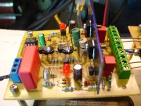
OK boys this second NAD channel is singing.
I believe to have a stereo amplifier tomorrow ,unfortunatly with common PS at this time.
"Any of the Toshiba/Sanken MT-100 (to-3p) will work here"
What about MT-220?
I believe to have a stereo amplifier tomorrow ,unfortunatly with common PS at this time.
"Any of the Toshiba/Sanken MT-100 (to-3p) will work here"
What about MT-220?
Attachments
Last edited:
I did build the SymAsym TO3 that sounds soooo good , and I have some difficulty to believe that any amp could sound really much better.
A faster (better) SYM , at normal volumes (8R) .... might be quite
indistinguishable from the original.
The original ran at 6-7ma VAS , drove a EF2 , and had 50v/us slew.
This one runs 4-5ma , has that compound cascoded wilson (V/I are separate).
Impedance is higher ... but it's running the HK680/slew EF3.
I do feel that everything (sound quality)would stay the same.
This is the main reason for improving the VAS ......
the original sym VAS underperforms at 120v p-p + .
At 300W+ , the original CAN'T do this with respectable THD . 😱 It was not designed for it.
It is also easier to choose devices here , the active differential (the I) needs
only low voltage (40-80Vceo), while the Voltage (cascode/wilson) does
all the "heavy lifting" (180-300Vceo).
The CM for the wilson can also be low Vceo complements of
the active differential - ksa1015/ksc1815 or ksa992/ksc1845 pairs.
A balanced superior VAS that splits the conversion job into
both parts and can go to 160v p-p - that is the goal here !
I also compensated like the HK680/Sansui with lag/lead/miller. This
allows faster slew and is stable for 30+ years (reliable -Z3900).
For a simple 48 parts - it can't be beat.
PS - this will power my SUB - it is bass "friendly" 😎 .
OS
OS
OK boys this second NAD channel is singing.
I believe to have a stereo amplifier tomorrow ,unfortunatly with common PS at this time.
"Any of the Toshiba/Sanken MT-100 (to-3p) will work here"
What about MT-220?
Electrically , they would work ...
but only 2 pair would fit the 3 pair OPS , 3 pair would fit the "monster" ??
OS
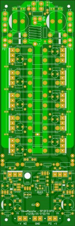
(below) is your board .. JK.
Larger pads + through hole for any device that might undergo
thermal cycling.
-All to-126/to-3p.
-Anything that will have physical stress.
-larger 1W power resistors (driver/predriver Re).
If something will "blow"... it will be these !!
- any "options" (boosted rails), that might get a future rework.
Just a few ideas...
OS
OK, later this evening I will beef up the art a little and re-export a new set of files as soon as I can. Anything else while I'm at it?
Good ! ...OK, later this evening I will beef up the art a little and re-export a new set of files as soon as I can. Anything else while I'm at it?
Any builder will have an "easy go" with that layout.
Easy to support on the tech side, as well.
PS - slightly larger pads for those hot (er... warm) resistors might be prudent.
OS
Thimios,
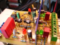
That looks nice but it appears there is barely enough room to fit the aluminum sinks and the led lights next to them.
That looks nice but it appears there is barely enough room to fit the aluminum sinks and the led lights next to them.
Yes it's a little problem here because of these .47uf big red WIMA capacitors.Thimios,
That looks nice but it appears there is barely enough room to fit the aluminum sinks and the led lights next to them.
Smallest capacitors (.68uf) will resolve this problem.
Last edited:
Thanks OS, but i will try to use these MT-220 under test conditions and then i will go for Spooky INP.😀Electrically , they would work ...
but only 2 pair would fit the 3 pair OPS , 3 pair would fit the "monster" ??
OS
Regards.
Thimios.
Last edited:
Good ! ...
Any builder will have an "easy go" with that layout.
Easy to support on the tech side, as well.
PS - slightly larger pads for those hot (er... warm) resistors might be prudent.
OS
OK, beefed everything up and went all PTH. Only one issue, a ton of 'Silk Screen On Pad' DRC errors 🙁 which leads to a lot of clean-up work on the silk layer. Hang tight.
Is this possibly the one?
Folks,
Now all PTH, beefier pads on demanding components, thicker traces...
Should now be ready to run a toaster 😀. Please review, I will only put up gerbers if there are no issues brought up with these images. I haven't got confirmation of my order yet either, so I might be able to swap in these files...
Attachments
One of my silly questions here. Is there a reason or is it related to how things would look when layouts used tape that all the changes in direction of the traces are straight sections and not curved? I see all the cut corners around pads and things and wondered why none of this is done with radius curves?
Folks,
Now all PTH, beefier pads on demanding components, thicker traces...
Should now be ready to run a toaster 😀. Please review, I will only put up gerbers if there are no issues brought up with these images. I haven't got confirmation of my order yet either, so I might be able to swap in these files...
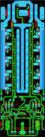
We seem to be as close as possible without getting "anal" ... here.
But I will.... 😀
The rail feeds to the collectors are double sided ... 12mm + combined.
With 1 oz copper , the combined sides have 16A capability each (10C rise) ..
The CircuitCalculator.com Blog PCB Trace Width Calculator
I calculated 20C rise/20A for 12.3mm - we are Good !
We would only see this worst case (or with "magic smoke"/short?) ... this is a DC
rating. Any fuse ,(for even the Semelab devices) would be 15A max.
You can omit the rail lines as that was for single sided augmentation.
The through holes between sides on the rails along the lines can
be single ones , as we are now "fat" (double sided - 12+mm total.)
The output traces are also fine (double sided w/ TH) , close to 12mm.
20A capable all the way .... 😎
OS
One of my silly questions here. Is there a reason or is it related to how things would look when layouts used tape that all the changes in direction of the traces are straight sections and not curved? I see all the cut corners around pads and things and wondered why none of this is done with radius curves?
You just have to worry about long parallel traces in "sensitive sections".
Like the predriver/driver/Vbe area (bottom of board).
Also , AC creepage between the 150v p-p output signal and any other
trace needs to be 1mm coated or 1.4mm bare .... we exceed this.
Curved lines and such are purely aesthetic , I do try to avoid right angles ,
but this is audio , not a PC motherboard 😀 .
PS -Member Alex mm showed me how to do curves on Sprint ... but it's
so "old school". 🙄
OS
- Home
- Amplifiers
- Solid State
- Slewmaster - CFA vs. VFA "Rumble"