Let's try this...
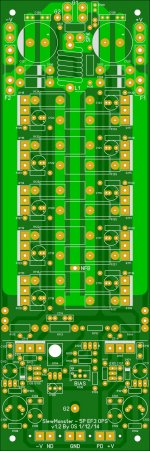
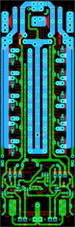
OK, multi-pitch back in for the OP decoupling capacitors and verified maximal clearance of 1mm is available, unnecessary 'stitching' pads removed from power rails, multi-pitch added to CM capacitor. Thoughts?
OK, multi-pitch back in for the OP decoupling capacitors and verified maximal clearance of 1mm is available, unnecessary 'stitching' pads removed from power rails, multi-pitch added to CM capacitor. Thoughts?
Attachments
I will go back over the file again and do an export shortly. I have a slightly earlier set already on order, so hopefully I can find some folks who are interested. No really big differences, just missing some of the multi pitch pads.
These are really cool! DIYA at its finest. I can see having a set on a couple big sinks sitting and waiting for the next cool front end. Probably all kinds of topologies that will just bolt up and fly, as OS puts it.
Blessings, Terry
Blessings, Terry
OK, multi-pitch back in for the OP decoupling capacitors and verified maximal clearance of 1mm is available, unnecessary 'stitching' pads removed from power rails, multi-pitch added to CM capacitor. Thoughts?
😎😎😎 3 cool ..
All hail the junkbox !! 😀
Still4given , I actually have over 20 IPS's I could "mate" with the "slewmaster" ...
Some would say that's silly , but it could be a good condensed decade
overview of DIYA AB designs.
I could even do uncle charlie's bootstrapped "blame" running into
an EF3 !
OS
He he. Well for me it would be great. I am getting quite a pile of boxes in my room. I'll never find homes for all of them. Having an OPS like this set up on heatsinks with speaker jacks and inputs ready to "plug in" the latest IPS.......well that's the DIYer's dream set up.
One other question. Is there a way to have the "jack" for the NFB somewhere more accessible? How do you go about plugging that in or do you have to solder it in each time?
Blessings, Terry
One other question. Is there a way to have the "jack" for the NFB somewhere more accessible? How do you go about plugging that in or do you have to solder it in each time?
Blessings, Terry
OS,
All you need is a thirty position switching box and all those input sections and you could do the ultimate blind listening test ! A great full range speaker system should give up a few selected ips in short order.
All you need is a thirty position switching box and all those input sections and you could do the ultimate blind listening test ! A great full range speaker system should give up a few selected ips in short order.
Realease the hounds! Er, Files?
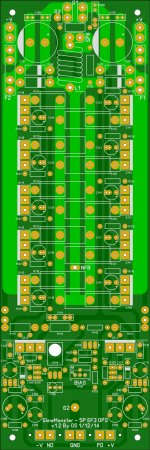
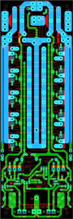
Are we ready? There were just a couple of very minor 'touches' just to satisfy me after not having looked at it for a few hours, mostly silk touch-up. I will post the files if OS thinks they are really ready.
Are we ready? There were just a couple of very minor 'touches' just to satisfy me after not having looked at it for a few hours, mostly silk touch-up. I will post the files if OS thinks they are really ready.
Attachments
do i smell a group buy? please count me in for 2 boards....
I think that is the ultimate plan. Myself and meanman1964 had a few words about it but nothing concrete as yet. However, I think we should consider keeping such traffic off this thread and open a new one in the appropriate place when the time is right. Managing that activity here would be a nightmare. My

I think that is the ultimate plan. Myself and meanman1964 had a few words about it but nothing concrete as yet. However, I think we should consider keeping such traffic off this thread and open a new one in the appropriate place when the time is right. Managing that activity here would be a nightmare. My
absolutely.....
may i suggest 2 oz. boards, FR4 boards about 2.8mm thick..
He he. Well for me it would be great. I am getting quite a pile of boxes in my room. I'll never find homes for all of them. Having an OPS like this set up on heatsinks with speaker jacks and inputs ready to "plug in" the latest IPS.......well that's the DIYer's dream set up.
One other question. Is there a way to have the "jack" for the NFB somewhere more accessible? How do you go about plugging that in or do you have to solder it in each time?
Blessings, Terry
Maybe a wire wrap pin ? Of all the modular connections , a screwed up
NFB would be the most catastrophic. Open loop hell !! 😀
PS - servo would push to rails , amp would oscillate fiercely .
OS
I'm sure a good solid locking connector could be found, either an 'in-line' type or a PCB mounted type. Heck, so long as it is snug, or doesn't become loose with repeated use, a spade would likely be secure enough.
Last edited:
OK, I probably just solder in a good size wire with a female spade connector on the end. Just seems strange that we have releasable connections for everything else and just a solder pad for this and it's sandwiched between the big resistors.
It's all good.
Blessings, Terry
It's all good.
Blessings, Terry
I would make the disconnect on the IPS and leave it soldered to the OPS, or do an in-line connection as you suggest.
I think OS just doesn't want to see the amp go 'open loop'. That has the potential to be baaad.
I think OS just doesn't want to see the amp go 'open loop'. That has the potential to be baaad.
That and I think the concept wasn't to be constantly switching / swapping the IPSs, but rather to allow a choice for the builder. Though I'm sure some of us will swap things about a few times....
Seeing as all these different input sections whether they are CFA or VFA can use multiple types of feedback topology, are we only going to have to bring a node back to the input stage where each implementation is then created? What if one is Cherry, another is Miller and any other number of schemes? Do we just have a lead wire from the OP section with a connector that can be attached to any type of feedback circuit?
Seeing as all these different input sections whether they are CFA or VFA can use multiple types of feedback topology, are we only going to have to bring a node back to the input stage where each implementation is then created? What if one is Cherry, another is Miller and any other number of schemes? Do we just have a lead wire from the OP section with a connector that can be attached to any type of feedback circuit?
Good question , KH.
Any of the local loop FB's take place on the IPS , any that include the OPS
return on "NFB". Of course , this also includes DC FB for the servo.
A compound OPS/local FB scheme is already included on some (NAD or
SYM). All the Hawksford based IPS's are "mini" loops (the hawksford is a FB
circuit)
The two I know about that would require something "special" ....
Predriver FB - like on the original leach. DC is fed back from the Main OP ,
signal FB is fed from a predriver node.
NO OPS FB - some designs don't include the OPS in the "loop".
VFA and CFA - the main FB loop only differs in impedance and current.
VFA is (higher) Z , only uA's of current returns to the IPS .... CFA has
a higher current return 20+ma!! ... You notice my CFA IPS's have more space at
NFB plus the return is direct to G2 (bypassing the lifted ground).
All would be easy to implement with the existing setup.
OS
- Home
- Amplifiers
- Solid State
- Slewmaster - CFA vs. VFA "Rumble"