Thanks OS.
Can there be multiple global feedback points integrated into the op board depending on if you are using a node at the predriver or if you are doing output inclusive feedback? I only know so much so I am just asking questions that perhaps most others already understand. I need to read the Cordell book a few more times and D. Self's book also. So much to learn!
Can there be multiple global feedback points integrated into the op board depending on if you are using a node at the predriver or if you are doing output inclusive feedback? I only know so much so I am just asking questions that perhaps most others already understand. I need to read the Cordell book a few more times and D. Self's book also. So much to learn!
The nad feeds back HF from the VAS to the inverting current FB node
on one of the input pairs through a capacitor.
The CF resistors just feed back signal from the OPS within (under) the bandwidth set by this capacitor.
The normal VAS (miller) is just like a servo integrator but at a much
higher freq. Nothing (or less) gets past the VAS over a set freq.
Sort of like an OP-amp low pass filter ... just think of these designs as
HUGE op-amps. 😀 The only difference is that the "innards" are all out in
the open.
This is why we can "devastate" chip amps (performance wise). 😎
PS - the "symasui" is a HUGE ne5532 IC , and the "blameless" (wolverine)
is a HUGE TL071/72 IC ..... same circuits !!!
OS
Thanks again,
So much to learn. I have a bunch of the 5532 opamps for the active XO's that I have yet to build. The more you all communicate back and forth the more I learn.
So much to learn. I have a bunch of the 5532 opamps for the active XO's that I have yet to build. The more you all communicate back and forth the more I learn.
Are we ready? There were just a couple of very minor 'touches' just to satisfy me after not having looked at it for a few hours, mostly silk touch-up. I will post the files if OS thinks they are really ready.
Hi Jason what did you say for some pads under the drivers heatsink in order this isn't flying?
Attachments

Last edited:
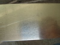
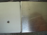
My first try in aluminium anodize.
First picture ,aluminium before anodize
Second,aluminium after anodize.
Third ,left after ,right before.
Sorry ,i know this is of topic but this ampl. deserves a beautiful heatsink!
First picture ,aluminium before anodize
Second,aluminium after anodize.
Third ,left after ,right before.
Sorry ,i know this is of topic but this ampl. deserves a beautiful heatsink!
Attachments

Last edited:
The nad feeds back HF from the VAS to the inverting current FB node
on one of the input pairs through a capacitor.
The CF resistors just feed back signal from the OPS within (under) the bandwidth set by this capacitor.
The normal VAS (miller) is just like a servo integrator but at a much
higher freq. Nothing (or less) gets past the VAS over a set freq.
Sort of like an OP-amp low pass filter ... just think of these designs as
HUGE op-amps. 😀 The only difference is that the "innards" are all out in
the open.
This is why we can "devastate" chip amps (performance wise). 😎
PS - the "symasui" is a HUGE ne5532 IC , and the "blameless" (wolverine)
is a HUGE TL071/72 IC ..... same circuits !!!
OS
OS,
Just tell us which IPS is your favorite?
thimios - Nice work, well done!!!!
Output Stage:
on the OPS would it be possible to have pads etc for appropriate connectors to be used for the NFB? For example something like:
1212 - KEYSTONE - TERMINAL, SPADE PCB | Farnell UK
Cheers
Rob
Output Stage:
on the OPS would it be possible to have pads etc for appropriate connectors to be used for the NFB? For example something like:
1212 - KEYSTONE - TERMINAL, SPADE PCB | Farnell UK
Cheers
Rob
so a fly lead may be the only option? Was just a nice to have ad the OPS appears to have everything 🙂
If this goes go down the GB path then it may be worth checking if we can have a large batch but shipped to a few locations. See if that controls costs a little over having separate orders from different sides of the pond?
If this goes go down the GB path then it may be worth checking if we can have a large batch but shipped to a few locations. See if that controls costs a little over having separate orders from different sides of the pond?
Hi Jason what did you say for some pads under the drivers heatsink in order this isn't flying?
To what purpose? You can't solder the driver HS, which is usually aluminum, to the board unless you are using copper or brass instead. A set of plain drillings for physical mounting would be better. You would wave to go with either a very thin material to bend 'tabs' with mounting holes, or very thick that could be drilled and tapped 'on-edge'.
OS has said before that a little thin aluminum flashing material is all that is needed at this location, which the devices themselves can support.
Got an opinion, OS? Do I need to drop a few HS mounting holes in?
so a fly lead may be the only option? Was just a nice to have ad the OPS appears to have everything 🙂
If this goes go down the GB path then it may be worth checking if we can have a large batch but shipped to a few locations. See if that controls costs a little over having separate orders from different sides of the pond?
The shipping of quantity to multiple destinations will likely absorb much of the benefit of a large single order. Besides, once the order quantity gets over about 20 pieces the price gets pretty reasonable anyway. If someone is going to sweat (literally) a few dollars on the boards then a project of this size probably isn't on the radar anyway.
Pads added for a spade. That should be workable.
To what purpose? You can't solder the driver HS, which is usually aluminum, to the board unless you are using copper or brass instead. A set of plain drillings for physical mounting would be better. You would wave to go with either a very thin material to bend 'tabs' with mounting holes, or very thick that could be drilled and tapped 'on-edge'.
OS has said before that a little thin aluminum flashing material is all that is needed at this location, which the devices themselves can support.
Got an opinion, OS? Do I need to drop a few HS mounting holes in?
The VAS heatsinks are actually overkill. The typical Japanese OEM
equivalent is at most a pair of TO-92L devices (without heatsinks) ,
running at 3-4ma.
This was another reason to go the EF3 route. Same with the pre-drivers
.... to-92 is standard fare.
To choose to-126 and a thin (flashing) heatsink , 4.5ma VAS operating
current ...... heat should be not be an issue.
Having a thicker HS , while it does not hurt ... is also "overkill" ,
it's the surface area of the HS ... not the thickness , that determines C/watt.
On the main drivers , the TO-3P should hold up to a much larger HS.
A thicker one here might be good , as the larger device prefers a
VERY flat mounting surface.
(go ahead and add some holes JK ... 😎)
Running a low HFE OP setup (21193/4) , one may want to use a much larger
driver HS.
OS
OS,
Just tell us which IPS is your favorite?
As far as one (I've) both built and is fun to simulate - the SYM.
It's Sooooo cool to jack the rails to 135V+ and run 200V ac signals
at 20ppm.
NAF/thimios both built the NAD , it looks like Xmas (well lit ! 😀) and
it's a CFA 🙄 .
What would I choose ? , most likely the SYM for my sub and the
NAD/spooky for my full range.
While the NAD my be a contender , consider that a "spooky" is basically
a full HK990 2500$ amp (with reviews) when paired with the slewmonster.
If you want listening impressions and OFFICIAL audiophile info ,
google "HK990 review".
I feel it is 99% the same ... right up to the 5 pair ON semi - MJLxxxx
OPS.
My first try in aluminium anodize.
First picture ,aluminium before anodize
Second,aluminium after anodize.
Third ,left after ,right before.
Sorry ,i know this is of topic but this ampl. deserves a beautiful heatsink!
That works REAL good , T !!
They charge exorbitant fees for anodization - please explain the
process - that looks pro !! 😱
OS
Ok Peter i will try to explain with some photos soon or with a short video.
Just now i have find a similar process here:http://www.thefintels.com/aer/homealuminumanodizing.htm
Any singing Spooky out there?
Thimios
Just now i have find a similar process here:http://www.thefintels.com/aer/homealuminumanodizing.htm
Any singing Spooky out there?
Thimios
Last edited:
Ok Peter i will try to explain with some photos soon or with a short video.
Any singing Spooky out there?
Thimios
All the HK990's ??? 😀
All the same ....right down to the servo.
OS
I mean a singing OS Spooky🙂All the HK990's ??? 😀
All the same ....right down to the servo.
OS
Has someone a functional OS Spooky?
Last edited:
I have a question. I assume Q104 needs to be on the heat sink for thermal compensation. Can it be flown on wires and bolted to the top of one of the outputs?
Thanks, Terry
Thanks, Terry
Ostripper,
I am studying the schematic for your SpookyAmp v1.1 from post #803 and comparing it to the PCB. The only difference that I see is that D3 and D4 LEDs are wired to ground thru a diode rather between the bases of transistors as shown in the schematic. I presume that was on purpose.
My real question is to ask which resistors had you planned on not being 1/4W? I presume R25 & R26 are 1W rated. What about R26 & R28? I presume there are others. What have I missed? I'd rather not screw this up!!
And mica caps at C7 and C8. Anywhere else??
- Home
- Amplifiers
- Solid State
- Slewmaster - CFA vs. VFA "Rumble"