What would I choose ? , most likely the SYM for my sub and the
NAD/spooky for my full range.
Hi OS,
Did you find a measurement which might explain why the SYM would be better for bass?
THx-RNMarsh
I mean a singing OS Spooky🙂
Has someone a functional OS Spooky?
I don't have a spooky but my everyday amp "Pimped Citation 16" is very close in construction in that it has partial Leach DNA, it has CCS in the LTP tails, and it has Hawsford cascode VAS. Unlike the spooky it is not DC-servoed. I had 5 pairs of On-semi ThermalTrak in the OPS. This amp was first built as straight Leach Lo-TIM with ThermalTrak OPS a few years ago, I later mod-ed it by hard-wiring the CCS and Hawsford cascode into it. I took it to a gathering during the last x'mas where it stunned all by driving a pair of Maggie's. The track among the few played that impressed people the most was Murray Perahia on Prelude of English Suite No.6. Glorious piano sound! So no need to question the sound of spooky, it's simply wonderful. Go ahead and build it.
In the actual amp I use 2SA1360/2SC3423 in place of 2SA1381/2SC3503. I happened to have some of these flying around.
The complementary push-pull VAS works at a standing current that can drift over ambient temperature. That perhaps is not an issue unless one uses the ThermalTak diodes in the bias spreader as I did (Cordell's circuit). Because the VAS current passes through the two TT diodes and their forward drop varies if the current is not held constant, causing the considerable OPS bias current change. I had to carefully measure and test with different LEDs for the CCS and with different current settings so that the VAS standing current had a close to zero tempco. Just a little heads-up if anyone intends to try TT devices in the OPS.
Attachments
Last edited:
Hi OS,
Did you find a measurement which might explain why the SYM would be better for bass?
THx-RNMarsh
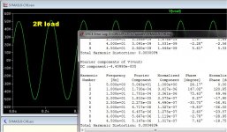
-It's tempco is the closest to zero , good for an enclosure.
-It's ability to create those HUGE waveforms with little thd degradation,
and the fact that it shows the lowest "blocker cap" THD at LF. (below)
-It's utter simplicity.
os
Attachments
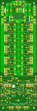
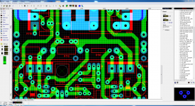
Ostripper,
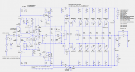
I am studying the schematic for your SpookyAmp v1.1 from post #803 and comparing it to the PCB. The only difference that I see is that D3 and D4 LEDs are wired to ground thru a diode rather between the bases of transistors as shown in the schematic. I presume that was on purpose.
My real question is to ask which resistors had you planned on not being 1/4W? I presume R25 & R26 are 1W rated. What about R26 & R28? I presume there are others. What have I missed? I'd rather not screw this up!!
And mica caps at C7 and C8. Anywhere else??
D5/D6 are 12V zeners ..all is correct here , they regulate the traces
connected to the servo,capacitors,cascode bases and CCS's/(leds ) .
R23/24 feed those zener diodes from the full rails ...
Maybe I should designate them "ZD5 / ZD6" 🙂 .
All the larger lead space resistor placements are best 1/2W+ ... R27 might
also be 1/2W depending on rail voltage/value.
Edit - yes , mica for Cdom1/2 (C7/8) ..
I think NAF already proofed and etched a pair of these.
OS
Last edited:
D5/D6 are 12V zeners ..all is correct here , they regulate the traces
connected to the servo,capacitors,cascode bases and CCS's/(leds ) .
R23/24 feed those zener diodes from the full rails ...
Maybe I should designate them "ZD5 / ZD6" 🙂 .
OS
Aah ...
I see now. Thanks!
Last edited:
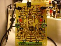
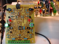
Spooky just before finish
Saved your good parts for the spook ??
😎😎
OS
Pete, may i have a question?
Which resistors must be changed on this Spooky for +/-45v?
Which resistors must be changed on this Spooky for +/-45v?
Last edited:
Pete, may i have a question?
Which resistors must be changed on this Spooky for +/-45v?
Maybe just a slight I increase to the green LED pair. And a slight
reduction of the dropping resistor value to the 12V zeners .
all that is +/-12V is rail independent.
OS
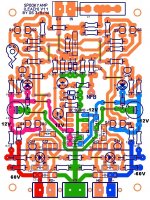
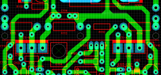
Mounting holes for the main driver HS, if needed. Does the positioning look OK? I have limited space so this looks like a workable place to have them.
If you want to do it ...
Find a TO-3p drawing , calculate the mm from the pins to the device
die plate ... add 2mm for the HS.
Then you will have an exact idea of available space.
PS - also just 1mm PTH holes would be better , you could use a solder based mounting
solution - or drill for screws...
OS
Last edited:
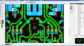
Everything is exported and ready. If this gets the 'Green Light' I will pit up the ZIPs with the required files.
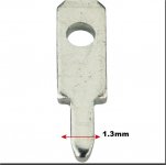
here is what I meant about a solder based mounting system.
Vogt Verbindungstechnik 3780A08.68 Solder Spade Connector from Conrad Electronic UK
One of these (above link/below pix) ... screwed to the HS and
soldered into The PTH holes - the holes would be 1.3mm dia. and be
behind the 2mm HS.
These can also be salvaged from old CRT/TV vertical and horiz.
PCB mount heatsinks 🙂 .
PS - just one of these in the middle hole ... combined with the 2 to-3p
devices ... would hold the HS VERY securely.
OS
Attachments
Last edited:
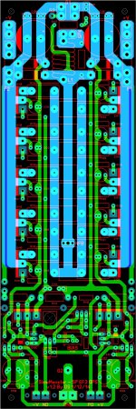
OK, the holes need to move a little. I am indisposed for about 2hr, I'll have to get to it a little later.
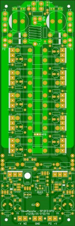
Good .. just -Holes moved for potential solder mount pins. on the driver HS.
Smaller pads (with the same 1.3mm holes) -Too close to those "ungodly" rail voltages
near those 1W resistors (R114/115). 😀
OS
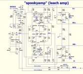
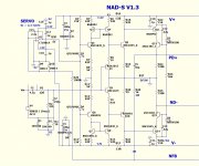
NAD-S v1.3
Member Dadod's input pair works. 🙂
FULL current FB for both stages (inv. and non-inv.).
I added my servo'ed CCS/CM , kept the 1 cap compensation , and
the 12V low voltage supply.
Single digit PPM is now normal for this design - matches the "spooky". 😎
It should fit the same layout as the V1.2 with minimal changes.
PS - the V1.2's servo arrangement is also very good , as the diamond's input is
very sensitive to the smallest offset. It only needs to offset a few mV's ...
The 1.3 bypasses ANY DC feedback into the signal path by adjusting the
CCS/CM circuit(s). The CM's also increase PSRR.
OS
Attachments
- Home
- Amplifiers
- Solid State
- Slewmaster - CFA vs. VFA "Rumble"