I will use the irfp even because I can't find the bjt here, what are the modifications to use the irfps?
You can find the start of it in post #3712
https://www.diyaudio.com/forums/solid-state/248105-slewmaster-cfa-vs-vfa-rumble-75.html#post4014254.
And in post #3795
Slewmaster - CFA vs. VFA "Rumble"
I built it with 5 pair and it works very well.
Slow power transistors need to be cross-coupled or use a very small base resistor (shunt ~10 Ohms). See Crown DC 300 back when all big transistors were slow.
Last edited:
would have pictures of the amplifier, it would be easier for me lookingYou can find the start of it in post #3712
https://www.diyaudio.com/forums/solid-state/248105-slewmaster-cfa-vs-vfa-rumble-75.html#post4014254.
And in post #3795
Slewmaster - CFA vs. VFA "Rumble"
I built it with 5 pair and it works very well.
Bob Cordell suggests that there isn't enough current flowing through the drivers to be able to completely switch old slower output devices off properly in this amp, causing shoot through and self destruction.
I think better make higher current on drivers than add "speed up" capacitor to make output device off properly. But I like use both 😀
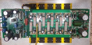
Here is a picture of mine. It is not the Arcwelder but the parts are the same.
congratulations on the assembly, know how to inform me if I can use NJW0281G (NPN)
NJW0302G (PNP) both 30mhz
in place of mjl / irfp?
I think better make higher current on drivers than add "speed up" capacitor to make output device off properly. But I like use both 😀
Hi bimo, take the official schematic, modify this according to your <<taste>> then post this here.
This way will be easy for us to follow.
I still have prototype boards. Easy to modify. 😉
congratulations on the assembly, know how to inform me if I can use NJW0281G (NPN)
NJW0302G (PNP) both 30mhz
in place of mjl / irfp?
Yes you can, i had used this combination too.
does anyone have tips for transitors that I can use on the way out? mjl / njw here they are very expensive
TTC5200, TTA1943?
You can use two pairs only, if you will use lower power supply.
Even one pair per chanel it's enough for +/-35V if 8 ohm speaker will be used.
Some resistors need trimming for lower voltage.
You can use two pairs only, if you will use lower power supply.
Even one pair per chanel it's enough for +/-35V if 8 ohm speaker will be used.
Some resistors need trimming for lower voltage.
Hi bimo, take the official schematic, modify this according to your <<taste>> then post this here.
This way will be easy for us to follow.
I still have prototype boards. Easy to modify. 😉
I have many design which I share to local audio community, but design usually simple with easy to find transistors. PCB layout made by others.
I also made design for a friend with high slew rate and low distortion. Usually, the main problem is PCB layout. One of my amplifier used in a house close to 2 radio transceiver and have RF interference. But it solved now. Recently, I made small class A, and it have small oscillation around 20MHz.
I think it already many design here. But I will consider your request.
I think it already many design here. But I will consider your request.
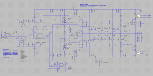
After I designed Pelatuk OITPC VMOS which tested by Thimios, now I design symmetric topology with OITPC compensation.
Target of this design is:
- high enough slew rate
- low enough distortion
- high PSRR
- simple as possible
This amplifier can drive 2 ohm load impedance and have SOA protection which it can seen it one my picture. SOA protection is active low (activated when saturated).
Attachments

Today i have a very-very good news for all of you Slewmaster guys!
I had a personal message from Pete (Ostriber)!!!
He is healthy, corona free!
I hope he will be here again soon. 😎
Well come Boss.
I had a personal message from Pete (Ostriber)!!!
He is healthy, corona free!
I hope he will be here again soon. 😎
Well come Boss.
Last edited:
- Home
- Amplifiers
- Solid State
- Slewmaster - CFA vs. VFA "Rumble"