Waiting for some explanation....
Hi..
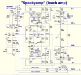
My objective is to make Spooky-Leach to work at +/-35V with 2 pair output.
Can somebody teach me how to change the VAS biasing?
Should I change R25/R29?
I wish to learn more details on the Hawksford cascode stage and how to set the VAS current.
Also, is there any change required for capacitance multiplier biasing resistors for 35V?
Thanks and regards,
Sumesh
I wish I can help you but I'm more like a PCB designer guy 🙂 well ... I use the Greenamp on a 25V DC supply and it was working just fine maybe I'm wrong but it sound it good indeed maybe the guys are ocupied doing other things
Hi Sumesh,
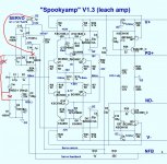
You need to change:
R23, R24
R22, R27
No other changes required.
Assuming you need to maintain the same current through all these resistors, you need to re-calculate their values in proportion to the voltage change.
Cheers,
Valery
Thank you,
I learned how to calculate R23, R24, the rail dropping resistors, assuming 21mA current(LTP+ servo OPamp current) through them.
I couldn't find how to set values for R22,R27.
Any help in this would be great.
Thanks and regards,
Sumesh
I learned how to calculate R23, R24, the rail dropping resistors, assuming 21mA current(LTP+ servo OPamp current) through them.
I couldn't find how to set values for R22,R27.
Any help in this would be great.
Thanks and regards,
Sumesh
Hi Sumesh,
You need to change:
R23, R24
R22, R27
No other changes required.
Assuming you need to maintain the same current through all these resistors, you need to re-calculate their values in proportion to the voltage change.
Cheers,
Valery
With 85V rails and 6.8K resistors, you will get around 17V at the zener, which should be fine.
Hari
You have a PM.. Please check...
Please always post the schematic diagram you will ask about.
This is a long thread for easy service.
If my memory serve well, you need about 5.5mA VAS current.
Voltage on a zener must be what a zener voltage is.
17v on a 15v zener isn't right. You must recalculate Rzener for 14, 8-15,2 voltage.
This is a long thread for easy service.
If my memory serve well, you need about 5.5mA VAS current.
Voltage on a zener must be what a zener voltage is.
17v on a 15v zener isn't right. You must recalculate Rzener for 14, 8-15,2 voltage.
Last edited:
You have a PM.. Please check...
Sumesh
Have replied with my contact details.
Hari
Spooky leach started singing...
Thanks for all the support...Got my doubts cleared after reading the previous posts in the thread....!
Now, only ONE doubt...Where should I connect the servo ground? To the lifted signal ground or to the main IPS ground G2?
I understand that feedback ground should be connected to lifted ground.
Pls, clarify.
Thanks and regards,
Sumesh
Hi Sumesh,
You need to change:
R23, R24
R22, R27
No other changes required.
Assuming you need to maintain the same current through all these resistors, you need to re-calculate their values in proportion to the voltage change.
Cheers,
Valery
Thanks for all the support...Got my doubts cleared after reading the previous posts in the thread....!
Now, only ONE doubt...Where should I connect the servo ground? To the lifted signal ground or to the main IPS ground G2?
I understand that feedback ground should be connected to lifted ground.
Pls, clarify.
Thanks and regards,
Sumesh
Attachments
Thanks for all the support...Got my doubts cleared after reading the previous posts in the thread....!
Now, only ONE doubt...Where should I connect the servo ground? To the lifted signal ground or to the main IPS ground G2?
I understand that feedback ground should be connected to lifted ground.
Pls, clarify.
Thanks and regards,
Sumesh
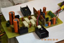
I think you can connect that normally my Greenamps I connected them in the same matter the servo GND is already establish see image
Attachments
Thank You Juan...It helped...
I think you can connect that normally my Greenamps I connected them in the same matter the servo GND is already establish see image
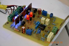
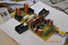
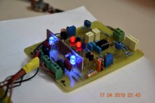
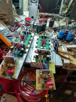
Spooky Leach 1 pair @ +/-32V
Hi...
Extremely happy with the Spooky build...
Express sincere gratitude to W. Marshall Leach, Jr, OStripper, and Spookydd, Valery, Juan, Thimios,Terry, Sownel, Jethari, Andrew Lebon and many others who have helped me indirectly.
All voltages are in accordance with OS's simulated values.
DC Offset 1-3mV
Thanks and Regards,
Sumesh
Attachments
Hi...
Extremely happy with the Spooky build...
Express sincere gratitude to W. Marshall Leach, Jr, OStripper, and Spookydd, Valery, Juan, Thimios,Terry, Sownel, Jethari, Andrew Lebon and many others who have helped me indirectly.
All voltages are in accordance with OS's simulated values.
DC Offset 1-3mV
Thanks and Regards,
Sumesh
Congrats Sumesh.. nice build 🙂
Regards,
Sha
Hi...
Extremely happy with the Spooky build...
Express sincere gratitude to W. Marshall Leach, Jr, OStripper, and Spookydd, Valery, Juan, Thimios,Terry, Sownel, Jethari, Andrew Lebon and many others who have helped me indirectly.
All voltages are in accordance with OS's simulated values.
DC Offset 1-3mV
Thanks and Regards,
Sumesh
Good show Sumesh, way to go

Hello everyone
I finished reading the whole thread:
overwhelming and engaging, wonderful people, wonderful projects, wonderful brains ... you have thrilled me with such team spirit ... you are my "virtual family", congratulations to all ... .. now I can start building the Slewmaster.
Ciao
Paolo
PS:I would like to buy a pair of OPS 3P pcb, does anyone have availability?
OK.
In my version of this VAS , the global bias is usually set by the current in
the LTP's. If you want a set LTP current , there is a alternative way to
fine tune the cascode's (VAS main output I) current. That is to change the
amount of current through the LED's.
Calculating the main current is as simple as subtracting the LED current from
the current across one of the main VAS emitter resistors. If you want less
current through the cascode , reduce R between the LED's.
As far a the Cap multiplier with a lower supply , one could reduce the R (C-B)
to lessen the multiplier's voltage drop.
Also , at lower voltages the 12V zener regulator resistance need to be reduced.
35V = 2.2K - 3.3K.
PS - glad Y'all enjoy the spooky/greenamps. 🙂
OS
Both greenamps and the spooky use the hawksford cascode.Originally Posted by sumeshak
Hi..
My objective is to make Spooky-Leach to work at +/-35V with 2 pair output.
Can somebody teach me how to change the VAS biasing?
Should I change R25/R29?
I wish to learn more details on the Hawksford cascode stage and how to set the VAS current.
Also, is there any change required for capacitance multiplier biasing resistors for 35V?
Thanks and regards,
Sumesh
In my version of this VAS , the global bias is usually set by the current in
the LTP's. If you want a set LTP current , there is a alternative way to
fine tune the cascode's (VAS main output I) current. That is to change the
amount of current through the LED's.
Calculating the main current is as simple as subtracting the LED current from
the current across one of the main VAS emitter resistors. If you want less
current through the cascode , reduce R between the LED's.
As far a the Cap multiplier with a lower supply , one could reduce the R (C-B)
to lessen the multiplier's voltage drop.
Also , at lower voltages the 12V zener regulator resistance need to be reduced.
35V = 2.2K - 3.3K.
PS - glad Y'all enjoy the spooky/greenamps. 🙂
OS
Hi all...
I started to populate "Arc Welder" edition. Is there a reason to use 5 pairs in output with 2x50v rails (I will use 2 x 2x35v 300W each toroids for dual mono) or it's better to use 3 pairs of output transistors?
p.s. I already built "borys edition" of SlewMaster and tried it with several IPS - it's fantastic project! Huge Thanks to OS and everyone in this thread!
Thank You
- Home
- Amplifiers
- Solid State
- Slewmaster - CFA vs. VFA "Rumble"