Maybe some of your transistors are fakes? Swap them with some known real transistors. Don't give up, this is an amazing design and you've already gone too far to give up on it.
oh man I was thinking about that cause I use some transistors from Tayda Electronics I usually always order from Mouser all the semiconductors that most be the reason I'm gonna check the layout to see if I did something wrong but I know for sure that fine anyway is best if I double check the layout we humans after all I'll keep you inform 🙂 also did anyone order from Tayda electronics that have a problem with fake transistors?
Vargas
Hi Juan.... 😰😰😰 sad news with the greenamp board.
Steps I would use to check it.
1. Re check the layout against the actual circuit from OS.
2. Check the circuit on multisim matches the OS schematic.
3. If all is ok. Check if the circuit will run at 25v by using multisim.
4 . If it works on multisim then there is probably a problem with component placement. Check the PCB
5. Once the board is checked. Then use your multimeter and check the voltages around the board are close to the multisim schematic. This should 100% hi light the problem
Regards
Mr ST
zener regulators need a higher voltage to not lose voltage.as a second thoughts the reason that is not working properly is becuase the supply voltages is to low? 25V DC or go back the black board again oh Lord!
Vargas
R20/22 = 2.7 -3.3K @ 30-40V rails.
I noticed you used green led's for the CCS's , your differential sources
are at a much higher current with the 2.2-2.4V+ Vf of the green's.
Red's are 1.7 - 2V Vf.
OS
oh man that most be the problem I mess that up 🙁 make sences stupid me! you tested with 60V rails I'm using 25V DC no wander it din't work "I think" I think was because I was so concentrated not to mess it up that I forgot all about it to changed to 54V DC, I have a transformer that can give 54V DC I think I did use the smaller one as a "safe test" ok ok so what I'm gonna do is order the right led's I'm not gonna give up I still can do it at least there is audio coming out 😱
Vargas
Vargas
agree I have to see if there is also that a misplace components that can be too oh well I just need to be positive and keep on trayingHi Juan.... ������ sad news with the greenamp board.
sorry OS I forgot to ask if I'm gonna use 50 to 60 V DC R20 and R22 what would be the values?
last question of the night Puerto Rico local time, is this LED be ok?
Mouser part number 696-SSL-LX5093XRC-TR
SSL-LX5093XRC-TR Lumex | Mouser Puerto Rico
RED
Operating Supply Voltage:
1.7 V
Vargas
Attachments
hi vargas, this can also be an option, kingbright also provides 3ds files and your data is more complete
https://www.kingbrightusa.com/product.asp?catalog_name=LED&product_id=WP7113LID
digikey pn: 754-1266-ND
https://www.kingbrightusa.com/product.asp?catalog_name=LED&product_id=WP7113LID
digikey pn: 754-1266-ND
I'll take a look thank you
ok I order the parts the correct LED as OS mention 1.7 Red the one that Mr. BitIOrd recomended I just got to wait then 🙂
Vargas
ok I order the parts the correct LED as OS mention 1.7 Red the one that Mr. BitIOrd recomended I just got to wait then 🙂
Vargas
Juan please look here
Zener Diode Series Resistor Calculator
Keep in mind that zener voltage is for input and servo circuit only when VAS need the ful Rail voltage for proper operation.
Pete what is the I load?(servo&input current)
Sorry, what is the current consumption in the left place of R9, R10? (I zener+I load)?
Zener Diode Series Resistor Calculator
Keep in mind that zener voltage is for input and servo circuit only when VAS need the ful Rail voltage for proper operation.
Pete what is the I load?(servo&input current)
Sorry, what is the current consumption in the left place of R9, R10? (I zener+I load)?
at 25V DC rails is about 3.38mA positive and 3.30mA negative and zenervoltages yes too low +4.6 and -4.7 VDC
yeah man I wasn't thinking clearly it does make sense that is not gonna work properly with the supply voltages I have 25V DC and wrong LED OS mention that they need to be 1.7 - 2 fV I just order the correct LED last night that be my fault agree of what you saying "VAS need the full Rail voltage for proper operation."
but I do have a toridal that after rectification and filtering it give me about 54V DC that is the one I'm gonna use after I get the other board ready
Juan please look here
Zener Diode Series Resistor Calculator
Keep in mind that zener voltage is for input and servo circuit only when VAS need the ful Rail voltage for proper operation.
Pete what is the I load?(servo&input current)
yeah man I wasn't thinking clearly it does make sense that is not gonna work properly with the supply voltages I have 25V DC and wrong LED OS mention that they need to be 1.7 - 2 fV I just order the correct LED last night that be my fault agree of what you saying "VAS need the full Rail voltage for proper operation."
but I do have a toridal that after rectification and filtering it give me about 54V DC that is the one I'm gonna use after I get the other board ready
Thanks Juan but this a question for Pete.at 25V DC rails is about 3.38mA positive and 3.30mA negative and zenervoltages yes too low +4.6 and -4.7 VDC
If we know the I load we can calculate the value of R zener.
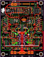
oh ok ok hey thimios I try with 54V DC rails and I have a bit more audio but I can not get more volume I have suspicious thinking that this transistors marked in green are fake cause I got them from Tayda Electronics they cost 6 cents each and I always usually order only from a trusted online stores like DigiKey or Mouser so that might be the problem but I will keep checking the layout probably I did something wrong another thing I really don't like to ask for favors but can some one take a look at the file to see if you guys can find the bug? by the way good new I just got the Arc welder PCB I'm gonna check the quality from JLCPCB 🙂
Vargas
Vargas
Attachments
Last edited:
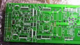
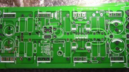
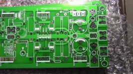
The Arc Welder sponsor JLCPCB
hello guys here are the photos of the Arc Welder this I didn't pay for them at least JLCPCB sponsor this PCB's I think the quality is great
Vargas
hello guys here are the photos of the Arc Welder this I didn't pay for them at least JLCPCB sponsor this PCB's I think the quality is great
Vargas
Attachments
Last edited:
Was there a reason why the Arc welder boards didn't have a LED on each rail?
Was it a space consideration, to only use only one LED on one of the rails?
Was it a space consideration, to only use only one LED on one of the rails?
this is actually the same layout I only did cosmetic changes but it is the same one 🙂
Vargas
Vargas
Have you measurements?
Is the led Lighting now?
Have you measure transistors between base emitter for. 0.6v voltage present?
Is the led Lighting now?
Have you measure transistors between base emitter for. 0.6v voltage present?
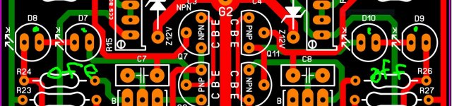
no yet thimios but none of the LED turns on I use a 54V supply voltage I have audio but too low and the only led's that turn on are D3 and D4 I'm a bit upset cause I know I spend a good time making sure that there are no errors on the layout maybe there is one bug but I can't see it, this image shows the image of the LED that does not turn on even with 54V supply voltage "I'm trying to keep myself positive" and figure it out this it must be something silly that I did, can be this reasons:
1. wrong LED's OS explain to be 1.7 Vf probably D8,7,10,9 are 2.4 Vf
2. misplace trace or connection
3. fake transistors can be Q7, Q8, Q11, Q12 this is from Tayda Electronics
4. wrong resistors value this happens a lot
so what I'm gonna do is keep checking the layout till a find that bug and killed!
Vargas
Attachments
Last edited:
Are you certain the LEDs are oriented properly? I have encountered devices where the polarity was wrong. If you have extras of the same just verify what the forward polarity is.
I thought about that too JK this is so weird 😕 oh yeah I do have extra LED's
maybe that is another reason agree JK
maybe that is another reason agree JK
- Home
- Amplifiers
- Solid State
- Slewmaster - CFA vs. VFA "Rumble"