I was reading the data sheet and I don't see any sentence that recomenended a 2 mm standoff? I know English is my second language what I understand is this sentence that said: "Mantain a minimum of 2mm clearance between the base of the LED lens and the first lead bend" and 2mm spacer? I don't think refers to a actual spacer is about a step before bending the leds I guess?
Vargas
For through-hole leds .... I think they want to keep the solder heat from
degrading the led junction. I've stood my led's off 5mm from the board ,
or clipped hemostats close to the body while soldering. This holds true
for any through -hole semi , the further away from the package you solder,
the less the damage.
PS - if you solder in <.5 seconds , it really won't matter.
These max. temp. -vs. time ratings are on the datasheets.
OS
For through-hole leds .... I think they want to keep the solder heat from degrading the led junction
OS
Yes. I got the wrong end of the stick. I was supposing heat dissipation in operation like a transistor but you're quite right it's really about not annealing the anode and cathode during soldering. I was looking at other led datasheets last night. Some indicate no spacing. Those that do, in the main, specify 2.00mm and some go down to 1.5mm.
any recomendation for C1 cap 4.7uF
hello OS or other members of diy community what type of cap you guys recommended for C1 4.7uF cap for the GreenampV1.2? I read that some guys use metalized caps? I really don't remember 😕
Vargas
hello OS or other members of diy community what type of cap you guys recommended for C1 4.7uF cap for the GreenampV1.2? I read that some guys use metalized caps? I really don't remember 😕
Vargas
Attachments

Last edited:
hello thimios MKP or MKT got it but not high voltage ones? no more than 50V or less right? thank for the replay 🙂
Vargas
Vargas
Hi vargas, you've seen the wima capacitors for audio, it has a good pdfhello OS or other members of diy community what type of cap you guys recommended for C1 4.7uF cap for the GreenampV1.2? I read that some guys use metalized caps? I really don't remember 😕
Vargas
Attachments
For this size, Panasonic ECW is very good choice (Mouser stocks two versions, the orange/red and the black).
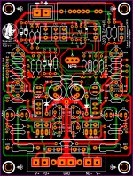
The V1.2 PCB update looks good.
How about a creepage check. Surely the output pads, positive and negative are to close together.
You may also be able to save some space if you use the small LEDs like the ones on the HB board.

How about a creepage check. Surely the output pads, positive and negative are to close together.
You may also be able to save some space if you use the small LEDs like the ones on the HB board.
thank you for the info I already order that brand Wima what a coincidence 🙂Hi vargas, you've seen the wima capacitors for audio, it has a good pdf
Vargas
hello ST yes the creepage to be honest I didn't I should but not this time, by the way that HB build looks amazing Mr. ST 🙂 okay about the changes they were a few details that I have to redone on the PCB this are fixed and yes definitely the leds I need to change them "since this is a prototype" I only can tested with audio if all goes well and working correctly I will order the final PCB version, that is PCB V1.1 and to be honest here in diy I have learn so much from you guys that I do not mind at all to share the files can be Sprint file and gerbersThe V1.2 PCB update looks good.
How about a creepage check. Surely the output pads, positive and negative are to close together.
You may also be able to save some space if you use the small LEDs like the ones on the HB board.View attachment 742424
 as longer you don't profit the design this is not my intention either this
  no no me learning more yes yes 🙂
Vargas
Attachments
Hi Juan.
I hope you are well. There is no doubt that you have done a amazing job on this board. You have done everything you can to make this board one of the best here on DIY. It a real credit to you and I'm sure that everyone here appreciates what you have done.
If you like I don't mind looking at the clearance and creepage for you. Once I am done I can send the Sprint layout file back to you. You could then review it.
If you want to use the file thats great. If you decide that you don't want to use it that's fine to.
But I think that if you or I review the clearance and creepage on this board it will only improve it.
Thank you for your kind words about the HB. I posted some other pictures on the HB thread.
Keep up the good work and yes learning is the best thing about DIY Audio.
no no Mr. ST not the best "You have done everything you can to make this board one of the best"
I can say is an ok design maybe? I'm just trying the best I can
"If you like I don't mind looking at the clearance and creepage for you"
sure no problem 🙂 Mr. ST that be great indeed
Best Regards
Juan
I can say is an ok design maybe? I'm just trying the best I can
"If you like I don't mind looking at the clearance and creepage for you"
sure no problem 🙂 Mr. ST that be great indeed
Best Regards
Juan
Well I think that most people on DIY would truly appreciate what you have done here and it would be difficult to improve on what you have done as the layout looks amazing. Every time I see it you have tweaked the tracks so nicely and put a lot of thought into how the final board looks and performs.
Just amazing. [emoji16]
Just amazing. [emoji16]
"If you like I don't mind looking at the clearance and creepage for you"
sure no problem 🙂 Mr. ST that be great indeed
Best Regards
Juan
If you can send me the Sprint layout file and the multisim file I will get started and I will be glad to give this awesome board of yours a creapage and clearance check for you.
do this transistors need to share temperature?
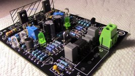
hey, guys, I have a question here is Q9 and Q10 the medium power transistor do they need to share the same heat sink or they can have separates small heat sinks? or like always a small aluminum sheet with both transistor attached to the sheet? I always have that in mind 😕
hey, guys, I have a question here is Q9 and Q10 the medium power transistor do they need to share the same heat sink or they can have separates small heat sinks? or like always a small aluminum sheet with both transistor attached to the sheet? I always have that in mind 😕
Attachments
hey, guys, I have a question here is Q9 and Q10 the medium power transistor do they need to share the same heat sink or they can have separates small heat sinks? or like always a small aluminum sheet with both transistor attached to the sheet? I always have that in mind 😕
Hi Juan. I have run some numbers for you. I measured the Power dissipation wattage of each transistor Q9 and Q10 in Multisim at full load and saw they are about 220mw each.
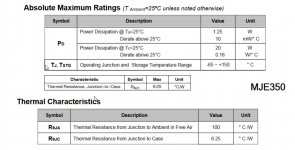
If we assume a Ambient Air Temperature of 30ºC From the datasheet you will see, the maximum junction temperature is 150º C and the Thermal Resistance from Junction to Ambient in Free Air is 100º C/W So, if each transistor dissipates 220mw then that is a thermal resistance to Ambient of 22ºC Then we need to add the thermal resistance of the Junction of the Transistor to its case. In this case the Transistor to case thermal resistance is 6.25°C/W which equals 6,25°C/W x 0.220 watts => 1.375º C
So if we add this all up we will get our total thermal resistance without a heat sink. Ambient Air Temp + Transistor Case to Ambient Air + Transistor Junction to Case = Total thermal resistance.
30ºC + 22ºC + 1.375ºC = 53.375º C which is a little over 1/3 of maximum. ---------------------------------------
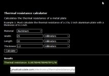
If we now run the numbers using a strip of Aluminum which is 30mm long x 25mm wide x 1.2mm thick (This is half of your available space as we are doing the calculations for one transistor)
The thermal resistance Heatsink to Ambient is 0.0078°C/W which equals 0.0078°C/W x 0.220 watts => 0.001716º C
I assume that you would use thermal grease so that needs to be added. The thermal resistance Case to Heatsink of thermal grease is about 0.2°C/W which equals 0.2°C/W x 0.220 watts => 0.044º C
Then we need to add the thermal resistance of the Junction of the Transistor to its case. In this case the Transistor to case thermal resistance is 6.25°C/W which equals 6,25°C/W x 0.220 watts => 1.375º C
So if we add this all up we will get our total thermal resistance Ambient Air Temp + Heatsink to Ambient + Transistor Case to Heatsink + Transistor Junction to Case = total thermal resistance.
30ºC + 0.001716º C + 0.044º C + 1.375ºC = 31.42º C which is only a increase of 1.42º C above ambient.
So in summary. I would use a heatsink . A strip of Aluminum will be fine 60mm long x 25mm wide x 1.2mm thick or simlar, but if you don't use one the transistors will be ok. They may just have a shorter life.
I would use them on the same strip to keep both the transistors at the same temp.
This video may also help YouTube
Hope that helps you. Regards Mr ST.
Attachments
Last edited:
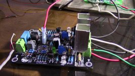
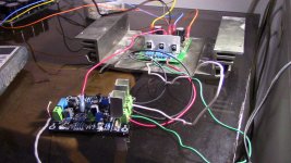
hello guys I think I fail my buid I tested with 25V DC supply voltage and it has sound but really low also none of the LED turn on at all I guess I made a mistake on the layout some how I belive I fail cause I remove the Greenamp and place the The Wolverine IPS boards and I have good sound, if the Wolverine work fine means the yes I fail this design like I said before I'll inform good or bad this time is bad news 🙁
as a second thoughts the reason that is not working properly is becuase the supply voltages is to low? 25V DC or go back the black board again oh Lord!
Vargas
as a second thoughts the reason that is not working properly is becuase the supply voltages is to low? 25V DC or go back the black board again oh Lord!
Vargas
Attachments
Maybe some of your transistors are fakes? Swap them with some known real transistors. Don't give up, this is an amazing design and you've already gone too far to give up on it.
- Home
- Amplifiers
- Solid State
- Slewmaster - CFA vs. VFA "Rumble"