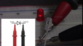
Are you certain the LEDs are oriented properly? I have encountered devices where the polarity was wrong. If you have extras of the same just verify what the forward polarity is.
Yes agree, i have some 3mm red leds with long lead as cathode.
That's why i ask about led Lighting.
Last edited:
Are you certain the LEDs are oriented properly? I have encountered devices where the polarity was wrong. If you have extras of the same just verify what the forward polarity is.
Yes agree, i have some 3mm red leds with long lead as cathode.
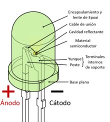
It is better not to rely on the length of a pin, it is better to identify with the multimeter or see the inner body of the led it is appreciated which is the anode and cathode, in the smd I have not noticed
Red LED are devils!
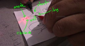
yes confirm!, the red LED that I use are backward they turn on if I place the positive probe to the cathode and black probe to anode this is crazy! what the heck!
yes confirm!, the red LED that I use are backward they turn on if I place the positive probe to the cathode and black probe to anode this is crazy! what the heck!
Attachments

Last edited:
I attach what should be the identification of the LED inside the package, but it is always better to identify with the multimeter, but if the LED is generic, for this reason it is good to buy good quality semiconductors that have a data sheet, like the one that tells you previously from kingbright
Last edited:
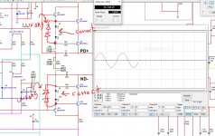
thank you 🙂 I just did a quick simulation with those LED reversed and I have just a few nW nano watts so LED D8,D7,D10,D9 have reversed leds this is so weird man even with 25V DC I should have at least 30W of audio with 357mV 1KHz sine wave 🙂 I hope this is the reason that why there is so low audio any way I'm gonna better wait for the proper LED that I order a few days ago that OS mention to be 1.7 fV and other members gave me the part number thank you
Vargas
Vargas
Attachments
Last edited:
is up ,and running damn! LED were reversed xD
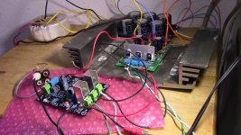
good good new guys the Greenamp V1.2 circuit PCB V1.0 is up and running sounds really good sorry about my ghetto set up is all I got xD so yeah reversed LED got me mess up oh Lord! really quiet no hum sounds at all wow! and is working from a 30V supply voltage 🙂
good good new guys the Greenamp V1.2 circuit PCB V1.0 is up and running sounds really good sorry about my ghetto set up is all I got xD so yeah reversed LED got me mess up oh Lord! really quiet no hum sounds at all wow! and is working from a 30V supply voltage 🙂
Attachments

very good, I lost track on this thread.
looks like a proto fired up for the first time, cool
Silly man get some cheap nylon standoffs instead of anti-static bubble wrap.
make note, THT led's the flag is always the cathode, some do not even have a flat spot.
pcb's done where?
looks like a proto fired up for the first time, cool
Silly man get some cheap nylon standoffs instead of anti-static bubble wrap.
make note, THT led's the flag is always the cathode, some do not even have a flat spot.
pcb's done where?
oh PCB are from PCBWay bro yeah this is was in a hurry I'll get those standoff yes man sounds amazing I'm still amazed by this  I need to check servo supply voltage from the servo with 54V DC and to check CCS adjustment
I need to check servo supply voltage from the servo with 54V DC and to check CCS adjustment
Last edited:
Use of conventional red leds are better ,red leds can be from 1,6 V to about 2 volt and green 2V im always test them.before i use and components ,its easy to be wrong.
Nice amp and good i think.
alcroner
Nice amp and good i think.
alcroner
Last edited:
I like stuartmp's write up for you on thermal's, that is as far back as I went.
I am using pcbway as well, the gerber viewer is nice to verify that all is well in reading in the data.
I am sure you have lots to check out, good luck with it.
No drinking while the power is on, treat like a chain saw, a toke is okay
I am using pcbway as well, the gerber viewer is nice to verify that all is well in reading in the data.
I am sure you have lots to check out, good luck with it.
No drinking while the power is on, treat like a chain saw, a toke is okay
believe it or not red leds are way more reliable than green. They are different types of semi's. I used to service a burn-in chamber at Motorola, there were red & green leds for status in the chamber. I always changed the green ones, hardly ever red. physics in action.
hahahahaha 😀I like stuartmp's write up for you on thermal's, that is as far back as I went.
I am using pcbway as well, the gerber viewer is nice to verify that all is well in reading in the data.
I am sure you have lots to check out, good luck with it.
No drinking while the power is on, treat like a chain saw, a toke is okay
let me be sure here the slewmini lateral mosfet that JKuteman did can work with 54V DC rail voltges right?
Will it work? Yes. Is that likely pushing one pair of output devices too hard? Yes also.
I'd say for functional testing into a resistive load or a well behaved speaker at moderate levels you are OK. For real-life use I suggest 45V rails are closer to optimum in terms of power and reliability, with lower rails improving reliability at the sacrifice of power.
I'd say for functional testing into a resistive load or a well behaved speaker at moderate levels you are OK. For real-life use I suggest 45V rails are closer to optimum in terms of power and reliability, with lower rails improving reliability at the sacrifice of power.
45V got it thank you JK 🙂 I think I have a transformer that after rectification and filtering 43V DC
Vargas
Vargas
hello OS since the I figure it out that the LED were reversed and the Greenamp is singing good  , I don't think I'm gonna order more but I add the SMD option on all LED last thing I add to the layout 🙂 thanks OS you are right it will sing is me that I reversed the LED xD
Vargas
, I don't think I'm gonna order more but I add the SMD option on all LED last thing I add to the layout 🙂 thanks OS you are right it will sing is me that I reversed the LED xDVargas
Attachments

Greenamp V1.2 circuit PCB V1.1 files
hello, guys, I posted the file on #10120
and I tweaked one last time all is in order is just a cheap LED that cause me lot of problems so I'm gonna attached the Sprint Layout 6 file here and gerbers if you want to try out I mean it sounds really good in my opinion yesterday I just got the "original parts from Mouser" so I'm gonna now populated the 2 boards I have with good parts the red LED that I have are oriented correctly this is PCB V1.1 the one from post #10120 is the old version, I add the option of using SMD LED on all also I add power indicator but that is up you if you wanna use can be skipped R34, D13 and R35, D14, the C1 input cap now is gonna have many options of pitch distance this are 5mm, 7.5mm, 10mm, 12.5mm, 15mm, 20mm, and 22.5mm also I add TP1 and TP2 the verified if U1 have the correct supply voltage the size is the same 76 mm x 100 mm. I order from PCBWay but also you can use JLCPCB is a lot cheaper PCB Prototype & PCB Fabrication Manufacturer - JLCPCB
I add the values cause when I was installing the components I have to go back and forward on the BOM and that got me stress out lol so I just add the values of the passive components among some semiconductors,also make sure to test the LED before you installed that also got me mess up too xD ok guys I have to move on to the Arc welder this might be the last post in this section about this layout I'm happy with it 🙂 good day
Best Regards
Juan
Attachments
Last edited:
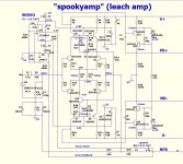
Hawksford cascode biasing--Sppoky at 35V
Hi..
My objective is to make Spooky-Leach to work at +/-35V with 2 pair output.
Can somebody teach me how to change the VAS biasing?
Should I change R25/R29?
I wish to learn more details on the Hawksford cascode stage and how to set the VAS current.
Also, is there any change required for capacitance multiplier biasing resistors for 35V?
Thanks and regards,
Sumesh
Attachments
- Home
- Amplifiers
- Solid State
- Slewmaster - CFA vs. VFA "Rumble"