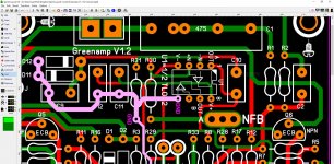
Greenamp IPS was a lazy creation to test my new OPS.
Just a simplified spooky IPS grafted on to that fancy
Baxandall/Hawksford VAS.
I was surprised at its 3ppm/1k 10ppm/10k 20ppm/20k
result. I LOVE the way it clips.
OS
Just a simplified spooky IPS grafted on to that fancy
Baxandall/Hawksford VAS.
I was surprised at its 3ppm/1k 10ppm/10k 20ppm/20k
result. I LOVE the way it clips.
OS
Looks great as always with your designs😊Greenamp IPS was a lazy creation to test my new OPS.
Just a simplified spooky IPS grafted on to that fancy
Baxandall/Hawksford VAS.
I was surprised at its 3ppm/1k 10ppm/10k 20ppm/20k
result. I LOVE the way it clips.
OS
Can you now call this Ips for a refined/optimized spooky V3 design?
Can you give more technical data about this Ips?
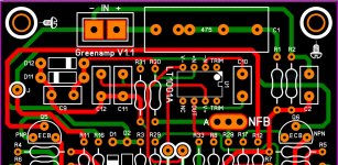
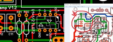
Thank you.Q1-4 = differential pairs
Q5-6 + D3-4 = LED based current sources.
Q7-12 = VAS - voltage amp stage.
IC U1 = servo.
OS
Hey , Vargas . I had no idea you would do a separate IPS of the greenamp.
It is absolutely slewmaster compatible.
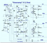
(below) is the final. It should be close to your present work. Sorry for
letting you work on a unfinished design.
PS- R15 and R18 are 200 or 500R 10 turn trimmers. They adjust both LTP and VAS standing
current. 130R is for simulation purposes.
OS
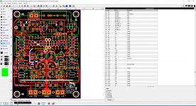
oh thank OS for the updated schematic, oh yes is gonna be a separate IPS, R15 and R18 200 to 500 ohms got it 🙂 I have a few more components to go or better say check, you think if I attached the sprint file here you guys can do a revision and help me out a bit to make sure is correct? cause the only area of the circuit that worried me is the servo U1 connections
Attachments
Looks great as always with your designs��
Can you now call this Ips for a refined/optimized spooky V3 design?
Can you give more technical data about this Ips?
Lazy creation tech data ?
It is a less refined spooky. The super-pair VAS is what allows it to
match the spooky.
I did it to eliminate half the devices of the spooky , while still retaining
that performance level. I have seen this raw 4 device input arrangement in
cheap subwoofer plate amps. Driving just a 2 transistor VAS and with no
current sources or servo.
I was kind of amazed that this VAS allows such a simple circuit to do
3ppm at 10Khz full power. The Kypton ND is the CFA equivalent.
Thimios built that. This one is guaranteed to work as advertised.
OS
oh thank OS for the updated schematic, oh yes is gonna be a separate IPS, R15 and R18 200 to 500 ohms got it 🙂 I have a few more components to go or better say check, you think if I attached the sprint file here you guys can do a revision and help me out a bit to make sure is correct? cause the only area of the circuit that worried me is the servo U1 connections
R15-18 = trimmers.
You can read the VAS current with R23 , then subtract R25 current to
get the REAL VAS current at the Q9/10 collectors.
LED'S (R25) use about 1.5ma of this VAS's total current.
If you overload this VAS it will cool down and the leds will blink.
Your output on overload will look rounded smooth instead of the
normal harsh transistor clip.
OS
taking notes thank you 🙂
Would it be possible to update the first post to reference the post # where the final version of the OPS schematic & PCB are? I am specifically interested in the 2 pair version. Having trouble locating it in the 10,000+ posts.
Thanks!
Thanks!
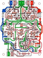
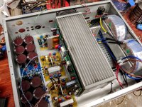
hello guys this is what I got so far I'll continue tomorrow 🙂 is not done yet
Attachments
Last edited:
hello guys this is what I got so far I'll continue tomorrow 🙂 is not done yet
Just a suggestion.OS uses simple to find dual opamp TL072 as servo in all of his IPS's.You can use it instead of LT1001A and configure the non used opamp as a unity gain buffer with the +input connected to ground.
Attachments
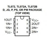
Just a suggestion.OS uses simple to find dual opamp TL072 as servo in all of his IPS's.You can use it instead of LT1001A and configure the non used opamp as a unity gain buffer with the +input connected to ground.
oh ok I will check that out 🙂
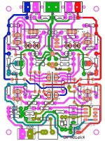
U1 TL072 pin number 5 to GND?
hello guys I just made the connection can you guys confirm that this is correct? so pin number 5 from U1 it goes connected GND? 😕 should I make the connection just like Kypto-C? I see pin 5 to GND pins 5 and 6 together and the rest normally connected I'll leave the sprint file 6 is you guys can help with this servo dilemma I will really apreciated 🙂
hello guys I just made the connection can you guys confirm that this is correct? so pin number 5 from U1 it goes connected GND? 😕 should I make the connection just like Kypto-C? I see pin 5 to GND pins 5 and 6 together and the rest normally connected I'll leave the sprint file 6 is you guys can help with this servo dilemma I will really apreciated 🙂
Attachments
Last edited:
It's a dual channel op-amp and because you are only using one of the of channels you need to basically disable the other one. You do this by making a unity gain amplifier out of the other unused opamp. The non inverting input is connected to ground.nice max hey that is nice 🙂
I will send you the pin number shortly. Hope that help you.nice max hey that is nice 🙂
hello guys I just made the connection can you guys confirm that this is correct? so pin number 5 from U1 it goes connected GND? 😕 should I make the connection just like Kypto-C? I see pin 5 to GND pins 5 and 6 together and the rest normally connected I'll leave the sprint file 6 is you guys can help with this servo dilemma I will really apreciated 🙂
Pin 5 to ground, pins 6 and 7 together and the rest normally connected. Here are the pcbs of Kypton-ND and Kypton-V2
Attachments

- Home
- Amplifiers
- Solid State
- Slewmaster - CFA vs. VFA "Rumble"