nice max hey that is nice 🙂
So all you need to do is connect the output of the second op-amp to the inverting input (-). You already have the non inverting (+) input connect to ground so that correct.
I sent you a picture.
Attachments
servo connection revision
thank a lot so this is final should we wait for the other guys to comment about this connection? 🙂 just in case 😉 thanks again Mr. ST
So all you need to do is connect the output of the second op-amp to the inverting input (-). You already have the non inverting (+) input connect to ground so that correct.
I sent you a picture.
thank a lot so this is final should we wait for the other guys to comment about this connection? 🙂 just in case 😉 thanks again Mr. ST
Attachments
Last edited:
thank a lot so this is final should we wait for the other guys to comment about this connection? 🙂 just in case 😉 thanks again Mr. ST
Yes I have used this connection on my Soft start board. Its what you need to do.
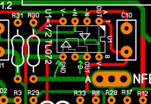
Maybe consider looking at your trace width and creepage as I found a few possible problems. But I did not check it against the multisim file.
But from experience you may able to reduce your trace width to get better creepage. See attache photo
Attachments
good thinking ST
I'll see what I can do since I made the layout on a small area is gonna be dificult to use creepage rules I will try my best to adjusted the best I can no problem man 🙂
Yes I have used this connection on my Soft start board. Its what you need to do.
Maybe consider looking at your trace width and creepage as I found a few possible problems. But I did not check it against the multisim file.
But from experience you may able to reduce your trace width to get better creepage. See attache photo
I'll see what I can do since I made the layout on a small area is gonna be dificult to use creepage rules I will try my best to adjusted the best I can no problem man 🙂
Pin 5 to ground, pins 6 and 7 together and the rest normally connected. Here are the pcbs of Kypton-ND and Kypton-V2
thanks maouna
both channels working... bias 70mA OPS and 2,4mA IPS ... just sold my old scope, so I will make some measurement, after that I will received my new one...
so let´s put it to chasis
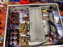
This is what I envision for the real "greenamp" class G.
You would have 700W x2 with the tunnel.
OS
thank a lot so this is final should we wait for the other guys to comment about this connection? 🙂 just in case 😉 thanks again Mr. ST
You do not have to use the second op-amp. I grounded the unused one
and set it as a buffer.
As a buffer doing nothing , IC uses about 7ma.
As a inline active buffer , IC uses about 12ma.
Adding the buffer does nothing to the servo filter Fc.
OS
sorry OS about my confusion if servo use 1/2 of the TL072 I'm using pin 1 = A OUT pin 2 -N pin 3 +N pin 4 is V- and pin 8 is V+ as usual so having pin 5 to GND and pins 6 and 7 connected will not make any diference and it will work just fine? sorry for keep the same subject over and over I just want this to be sure
Vargas
Vargas
yes Gerber and excellon not sure about cnc drill mfg 🙂Hi Vargas,
Is your software able to generate gerber, excellon cnc drill for mfg? -Rick
excellon is the cnc drill data
Okay it is sprint layout, damn I give you credit to draw these up referencing a ltspice schematic. No pin numbers on device to follow, man "OS" you make it hard for the layout department. 🙁 This is the way we did it 40 years ago 🙂
What is your 1/4W resistor lead spacing 10, 12.5mm?
Do you guys have any pcb outline standard to follow? FYI, I use 100x100mm since that is the max for the $2 for 10 special deal.
oh ok excellon ok, the 1/4W resistor have a pitch distance of 12 mm from pad to pad and I use only the Wolverine IPS board reference that jkuetemann made layout, the size is 76 mm x 100 mm and yes it was difficult but since I been doing this for about 5 years I got it this time even faster 🙂 good night is 12:59 AM time to sleep xD
Don't build my layout of the Greenamp V1.2
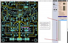
hello guys I still check the layout of the GreenampV1.2 please don't build it till I see all is correct I eventually order a few PCB to tested first I don't have a scope but at least put it together and tested with audio files so please don't build it, and I know that I post the sprint files here on this section for just revision only, Mr. OS most be really occupied doing the G-amp? I forgot, so I really don't want to bother him so he be concentrated on that, the layout I'm making is on me if I screw it up that be me no you guys so I'm gonna order and test it then I will let you know the result good or bad that be me if I made a mistake on the layout
Vargas
Attachments

Last edited:
If you look at post 10081 , the kypton's .... You see that I kept NFB away from any low level input. After the huge NFB waveform is reduced to a small one by either the 1M servo resistor or the 27-33k feedback resistor , it is ok to "mingle" with other small signals. Just something to consider. Look the layouts of my IPS's over , method to the madness.
OS
OS
NFB placement
I will take a look OS thanks, is that bad where a place the NFB faston terminal?, ok ok let me check post 10081, after check, I see what you mean the NFB faston or pad is preatty far away from the input I think I might be able to move down I hope so
Vargas
I will take a look OS thanks, is that bad where a place the NFB faston terminal?, ok ok let me check post 10081, after check, I see what you mean the NFB faston or pad is preatty far away from the input I think I might be able to move down I hope so
Vargas
Attachments

Last edited:
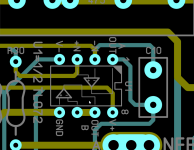
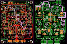
hello this is the last post about the servo U1 connections I found the layout of the Kypton - ND for what I understand pin 5 goes to pin 4 and 6 and 7 are going to be connected together is this correct? see image of the Greenamp V1.2 and Kypton - ND 🙂 I think my English is not clear 😀
Vargas
Vargas
Attachments

Last edited:
hello this is the last post about the servo U1 connections I found the layout of the Kypton - ND for what I understand pin 5 goes to pin 4 and 6 and 7 are going to be connected together is this correct? see image of the Greenamp V1.2 and Kypton - ND 🙂 I think my English is not clear 😀
Vargas
We have to move forward. (below).
Many of our beloved through hole components are obsolete , or about to become
that way.
A mix of through hole and SMD will have to be used to continue with our
hobby. Drivers, output devices , and electrolytic caps might be the only
survivors. All small signal , diodes , even leds ...smd.
The picture is representative of what the REAL greenamp might be like.
OS
Attachments

That is not mine , I will go denser.
Greenamp IPS might be a few postage stamps in size.
The output stage will have to be 5 X 15cm to facilitate big
components (caps , output transistors).
Some SMD is BIG. 5A dual Schottkey diodes are nearly TO-126 size.
OS
Greenamp IPS might be a few postage stamps in size.
The output stage will have to be 5 X 15cm to facilitate big
components (caps , output transistors).
Some SMD is BIG. 5A dual Schottkey diodes are nearly TO-126 size.
OS
- Home
- Amplifiers
- Solid State
- Slewmaster - CFA vs. VFA "Rumble"