I think i found this.No , thimios. Remember post #105 of this thread. (below).
Referenz = (below) ... minus the Hawksford.
positive servo fb + red led ccs.
I think you built it. So , you build it again. 🙄
OS
Slewmaster - CFA vs. VFA "Rumble"
Slewmaster - CFA vs. VFA "Rumble"
Last edited:
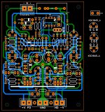
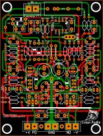
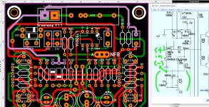
hello OS I decide to give a try to the new Greenamp V1.1 IPS I'm not done yet this is how it look for now 🙂
Attachments
Last edited:
there is an error on U1 supply connection ok let me continue this then it might change as I go 🙂
sir pls try to make single side pcb
I think is best if you wait for Mr. OS he got more knowledge than me I'm just learning just like everyone else if I completed this design successfully with no errors I do not mind at all to give the gerbers no problem at all, wait for OS he most be cooking something really good 🙂
hello OS I decide to give a try to the new Greenamp V1.1 IPS I'm not done yet this is how it look for now 🙂
I do a lot of double side layouts for audio. I'd say that you are doing a very good job!
Please keep it up and keep us posted as to your progress.
made a class g amp for car stereo in 97. 16v and 34v rails, this was a dual mosfet design using an op amp booster design and schottky diodes for the switches. the amp put out 2 * 125w into 4 ohms packed into a alpine 3522 case. ( 30w per channel)
this gave way to a master / slave arrangement with high performance class AB amp running in a class D envelope.
this gave way to a master / slave arrangement with high performance class AB amp running in a class D envelope.

caps and connection question
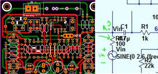
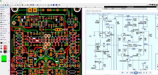
sorry I should add this other question on the last post OS, what is the resitor ID? I can't see what it is, also is this resistor need it on the circuit or it was just placed for analyzing the circuit with the sinewave ?
and lastly for the day is this connection correct of the audio input signal (+) and (-) placed correctly?
Attachments
Last edited:
Hello
greetings finally managed to assemble SPOOKY LEACH 5 pair output i will be
using 55 volt +/- dc rails can anyone help me with what should be bias voltage
across emitter resistance
warm regards
Andrew
greetings finally managed to assemble SPOOKY LEACH 5 pair output i will be
using 55 volt +/- dc rails can anyone help me with what should be bias voltage
across emitter resistance
warm regards
Andrew
sorry I should add this other question on the last post OS, what is the resitor ID? I can't see what it is, also is this resistor need it on the circuit or it was just placed for analyzing the circuit with the sinewave ?
and lastly for the day is this connection correct of the audio input signal (+) and (-) placed correctly?
No need for that 100R , I sometimes use multiple sines with a mixer.
+ and - is correct.
OS
Hello
greetings finally managed to assemble SPOOKY LEACH 5 pair output i will be
using 55 volt +/- dc rails can anyone help me with what should be bias voltage
across emitter resistance
warm regards
Andrew
12-15mV (each).
Idle current is independent of rail voltage.
OS
Should this layout and every thing "GreenAmp" related not be in the "GreenAmp ++ modulated Class G output" thread
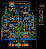
U1-7(V+) seems to only go to C11?
Something this complicated should have synchronization between schematic and layout to make it much easier to check other stuff rather than wondering if the layout netlist matches the schematic netlist.
Seriously OS, home etching is coming to an end when we can get pcb's done in Asia for very little. yes you need proper gerber/drill data but that ain't so hard these days.
Last edited:
Should this layout and every thing "GreenAmp" related not be in the "GreenAmp ++ modulated Class G output" thread
U1-7(V+) seems to only go to C11?
Something this complicated should have synchronization between schematic and layout to make it much easier to check other stuff rather than wondering if the layout netlist matches the schematic netlist.
Seriously OS, home etching is coming to an end when we can get pcb's done in Asia for very little. yes you need proper gerber/drill data but that ain't so hard these days.
OK , with the greenamp/OPS combo I will get serious if and when it is first
perfected,built and tested.
As a final project it will be an "all in one" PCB with gerber ,netlist , BOM.
I threw the greenamp IPS to this slewmaster thread to let it be tested
on the known separate OPS here. Free testing and confirmation of the simulation.
OS
thanks OS 🙂 hey I still looking for bugs so far I have not seen one yet I mean, you know 😀
Hey , Vargas . I had no idea you would do a separate IPS of the greenamp.
It is absolutely slewmaster compatible.
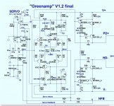
(below) is the final. It should be close to your present work. Sorry for
letting you work on a unfinished design.
PS- R15 and R18 are 200 or 500R 10 turn trimmers. They adjust both LTP and VAS standing
current. 130R is for simulation purposes.
OS
Attachments
Last edited:
Hi Mr OS,Hey , Vargas . I had no idea you would do a separate IPS of the greenamp.
It is absolutely slewmaster compatible.
(below) is the final. It should be close to your present work. Sorry for
letting you work on a unfinished design.
PS- R15 and R18 are 200 or 500R 10 turn trimmers. They adjust both LTP and VAS standing
current. 130R is for simulation purposes.
OS
Very interesting IPS design. Would it be possible to label some of the different building blocks of the circuit so less experienced people can work through it. Things like the differential pair transistors. Current mirror. VAS current source etc.
- Home
- Amplifiers
- Solid State
- Slewmaster - CFA vs. VFA "Rumble"