Softstart
Guy's I need some help plse. I have build this softstart circuit from Apex but I have a problem. I did not use the MOC 3041 but used MOC 3023 and the triac is a BTA40-600A . The triac does not fully switch on. There is a 2.8VAC volt drop across the 50R 20W resistor. I know some triacs have a 1 V drop to the load. Any ideas how to rectify this problem or is this normal.😕
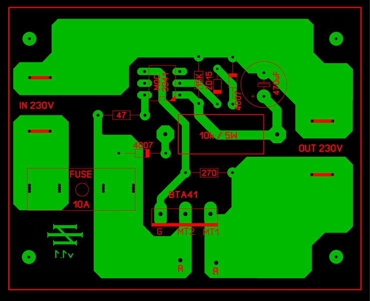
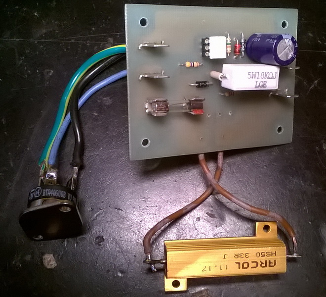
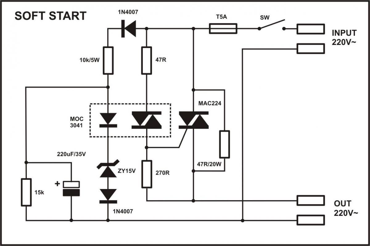
Guy's I need some help plse. I have build this softstart circuit from Apex but I have a problem. I did not use the MOC 3041 but used MOC 3023 and the triac is a BTA40-600A . The triac does not fully switch on. There is a 2.8VAC volt drop across the 50R 20W resistor. I know some triacs have a 1 V drop to the load. Any ideas how to rectify this problem or is this normal.😕
MOC3041 have built in zero crossing detector when MOC3023 not.Guy's I need some help plse. I have build this softstart circuit from Apex but I have a problem. I did not use the MOC 3041 but used MOC 3023 and the triac is a BTA40-600A . The triac does not fully switch on. There is a 2.8VAC volt drop across the 50R 20W resistor. I know some triacs have a 1 V drop to the load. Any ideas how to rectify this problem or is this normal.😕
Last edited:
Thimios, yes I know about that, I have just used what I had available, but is it the cause of the problem. I surely hope so. I will order the correct component.🙂
Thanks
Thanks

Spooky adventures
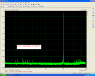
Then the signal and power gnd was separeted.
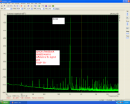
New measurements when feedback and servo reference is at signal gnd.
Then the signal and power gnd was separeted.
New measurements when feedback and servo reference is at signal gnd.
Attachments

Last edited:
Then the signal and power gnd was separeted.
New measurements when feedback and servo reference is at signal gnd.
Hi thimios, I saw big improvement here when compare with previous data. Could you specific about your grounding tech on:
- signal and power gnd mixed
- signal and power gnd was separeted
Thanks!
YES!
"Before" and "After" pictures of construction details would be great if you can
mlloyd1
"Before" and "After" pictures of construction details would be great if you can
mlloyd1
Hi thimios, I saw big improvement here when compare with previous data. Could you specific about your grounding tech on:
- signal and power gnd mixed
- signal and power gnd was separated
Thanks!
Hi thimios, I saw big improvement here when compare with previous data. Could you specific about your grounding tech on:
- signal and power gnd mixed
- signal and power gnd was separeted
Thanks!
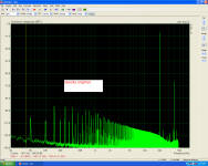
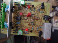
First picture is the Spooky ver.1.1 as built and tested in post #9584.YES!
"Before" and "After" pictures of construction details would be great if you can
mlloyd1
Second picture is the servo and feedback resistor reference in signal gnd.
Last picture the modified pcb.
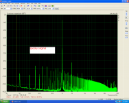
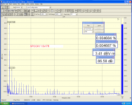
I must say that spooky have one of the most linear distortion curve that i have seen (see Steps on POST #9585 picture 3).
Attachments


Last edited:
I think feedback resistor go to signal ground was correct and been on new sp0oky schematic but I'm not sure about the servo. The new schematic still have servo ground connect to power ground.
So in summary you are done two mod and it is better. So not sure how each mod affect the final result.
So in summary you are done two mod and it is better. So not sure how each mod affect the final result.
I think feedback resistor go to signal ground was correct and been on new sp0oky schematic but I'm not sure about the servo. The new schematic still have servo ground connect to power ground.
So in summary you are done two mod and it is better. So not sure how each mod affect the final result.
The new schematic still have servo ground connect to power ground.
Where you see this?
C15 should still feed into Power Ground. Just like C13First picture is the Spooky ver.1.1 as built and tested in post #9584.
Second picture is the servo and feedback resistor reference in signal gnd.
Last picture the modified pcb.
I must say that spooky have one of the most linear distortion curve that i have seen (see Steps on POST #9585 picture 3).
I should have noticed the R31 connection to the Power Ground instead of the Signal Return ! But I was asleep each time I looked.
Does your "corrected" Signal Return connection get rid of the start up offset problem?
Last edited:
Hi AndrewT,Spooky haven't start up offset problem.This start up problem belongs to Symasui.C15 should still feed into Power Ground. Just like C13
I should have noticed the R31 connection to the Power Ground instead of the Signal Return ! But I was asleep each time I looked.
Does your "corrected" Signal Return connection get rid of the start up offset problem?
First picture is the Spooky ver.1.1 as built and tested in post #9584.
Second picture is the servo and feedback resistor reference in signal gnd.
Last picture the modified pcb.
I must say that spooky have one of the most linear distortion curve that i have seen (see Steps on POST #9585 picture 3).
Great work☺
Can you also make the same for Kypton ND and Symasui?
Could be Interesting to make new distortion comparisons and also what
Impact it will have on sound quality??
Kim
Symasui has been tested in three versions,one version with the original servo,second without servo and finally with a modified servo.Please see post#9567 ,9570,9571 for more details.Great work☺
Can you also make the same for Kypton ND and Symasui?
Could be Interesting to make new distortion comparisons and also what
Impact it will have on sound quality??
Kim
Last edited:
Why should the servo not be referenced to the supply zero point? how else could it null the output??
In my opinion only R31 should be connected to signal ground..
In my opinion only R31 should be connected to signal ground..
Hi!I must say that spooky have one of the most linear distortion curve that i have seen (see Steps on POST #9585 picture 3).
That's what I was talking about before. Servo on one of Opamp should be connected to a clean signal ground.
Last edited:
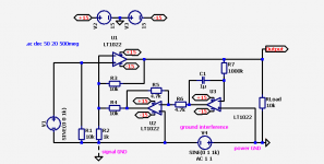
Engineers from Japan were very smart. Servo of two opamp by Onkio eliminated the interference on the ground (from V4) between the signal ground and power ground. See model. The servo suppresses the interference to -90 dB f=60 Hz and -40 dB at f=20 kHz. If you remove R4, the voltage of the interference on the ground will reach the output at the load.
V1 - no signal. R3=R4, R5=R6.
V1 - no signal. R3=R4, R5=R6.
Attachments
Last edited:
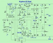
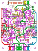
I'm working on my Kypton v boards and have run into some problems.
C16 and C17 0.1uF according to the schematics is nowhere to be seen on the board.
C13 is marked in two locations on the board.
is it correct that C13 and C14 next to the opamp should be 0.1uF?
C16 and C17 0.1uF according to the schematics is nowhere to be seen on the board.
C13 is marked in two locations on the board.
is it correct that C13 and C14 next to the opamp should be 0.1uF?
Attachments

- Home
- Amplifiers
- Solid State
- Slewmaster - CFA vs. VFA "Rumble"