i notice that the BC550 Q1. Q2 and Q3 have been replaced with KSC1845k in this schematic. is it necessary to replace them? Do i have to cross the pins to do so?
I see there's a lot of changes. Removering some resistors and replacing Q4 with led.
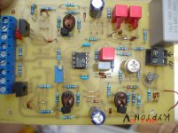
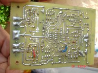
Thimios, do you have a picture showing what the board should look like after the modifications?
I built Kypton V2 final because it was posted in the first post and I thought that it had been tested and was working. Have anyone built that exact ips successfully?
http://www.diyaudio.com/forums/solid-state/248105-slewmaster-cfa-vs-vfa-rumble-539.html#post4126276
I see there's a lot of changes. Removering some resistors and replacing Q4 with led.
Thimios, do you have a picture showing what the board should look like after the modifications?
I built Kypton V2 final because it was posted in the first post and I thought that it had been tested and was working. Have anyone built that exact ips successfully?
http://www.diyaudio.com/forums/solid-state/248105-slewmaster-cfa-vs-vfa-rumble-539.html#post4126276
Last edited:
i notice that the BC550 Q1. Q2 and Q3 have been replaced with KSC1845k in this schematic. is it necessary to replace them? Do i have to cross the pins to do so?
I see there's a lot of changes. Removering some resistors and replacing Q4 with led.
Thimios, do you have a picture showing what the board should look like after the modifications?
I built Kypton V2 final because it was posted in the first post and I thought that it had been tested and was working. Have anyone built that exact ips successfully?
http://www.diyaudio.com/forums/solid-state/248105-slewmaster-cfa-vs-vfa-rumble-539.html#post4126276
You can use any high Ft BJT for Q1/2. The BC's are about the same if
you know the (1845) grades . BC550c is about the same as 1845 E or F grade. My 1845 E's were @ 380-400 hfe.
Thimios has it built , he showed it in this thread.
OS
Pete, please when you have the time look at post#9570,9571 where a two stage servo has been tested on the Symasui IPS.Hello , Thimios.
I am almost sure my posted "V2" is where you had it "singing" 😀 .
Right ??
I did update the R13 (servo FB) to coincide with the other
servo'ed IPS's (symasui/spooky) 5.6K Z allowed for millisecond settling.
Both my Symasui and spook settled to .1mv within <100mS with this
value.
OS
Last edited:
Are you speaking about Kypton v?i notice that the BC550 Q1. Q2 and Q3 have been replaced with KSC1845k in this schematic. is it necessary to replace them? Do i have to cross the pins to do so?
I see there's a lot of changes. Removering some resistors and replacing Q4 with led.
Thimios, do you have a picture showing what the board should look like after the modifications?
I built Kypton V2 final because it was posted in the first post and I thought that it had been tested and was working. Have anyone built that exact ips successfully?
http://www.diyaudio.com/forums/solid-state/248105-slewmaster-cfa-vs-vfa-rumble-539.html#post4126276
Yes. I built the one in post 5384 and can't get it to work. With nfb connected none of the leds light up. Without nfb connected one of them light up.Are you speaking about Kypton v?
I have double checked all values with the schematics and all of them match.
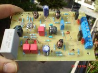
My Kypton v is on the post#5261 and the test is on the post#5282.Yes. I built the one in post 5384 and can't get it to work. With nfb connected none of the leds light up. Without nfb connected one of them light up.
I have double checked all values with the schematics and all of them match.
I can post some pictures tomorrow.
My Kypton v is on the post#5261 and the test is on the post#5282.
I can post some pictures tomorrow.
I see that you built your's before the schematics I used were published. Your version have more transistors and two more leds. Did you ever build the later version?
No,but if you read some posts after you can see that super pair has gone.I see that you built your's before the schematics I used were published. Your version have more transistors and two more leds. Did you ever build the later version?
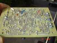
I have already read it. But I can't find any posts from people building the version I tried. I can rebuild mine to OS' latest schematic (will have to order some extra parts), but I'm affraid that there might be a bug in the layout causing problems if no one else have built it before. There was some errors in silk screen vs schematics, so I was expecting trouble with this IPS
If this will be useful.
Attachments
Last edited:
Nice the mat02 & your measuement supports data this in my opinon. Could you try the vindicator how it preforms incomparision to the other IPS.
BR. Toni
BR. Toni

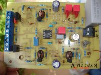
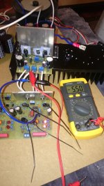
Voltages seems to be correct and I managed to adjust VAS to 5.5mV. The only differences I have from the schematic is R12 570R (470R+100R because I didn't have any 560R resistors) and C3 100p instead of 220p, since i forgot to order 220p caps.
It's powering the OPS now. Gonna put the scope on it and look for problems before I connect a speaker, remove light bulb and listen to music.
It's powering the OPS now. Gonna put the scope on it and look for problems before I connect a speaker, remove light bulb and listen to music.
Attachments

Glad to see your Krypton v working now!It's working and it sounds great. 🙂
What was the problem?
Is it a pcb bug to this v2 bord?
The problem was a solder bridge on Q1. 
It's still not perfect. After listening to music for a while, the bias suddenly goes sky high. (0.5V).
Both OPS and IPS is new, so I have to do more troubleshooting to find out if it's ips or ops related.
It's still not perfect. After listening to music for a while, the bias suddenly goes sky high. (0.5V).
Both OPS and IPS is new, so I have to do more troubleshooting to find out if it's ips or ops related.
Last edited:
The amp is stable now. I Increased R14 and 15 to 4.7k, after that the bias was fine.
Here's some scope shots. I couldn't clip it with my soundcard so I didn't see the clipping behaviour.


The square waves in was just as ugly as the output.

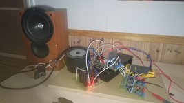
Looking forward to get a stereo pair up and running so that I can test it on my main speakers. This will be a mobile test rig mounted on a MDF sheet to test different IPS, when I'm done I will probably make it into a tweeter amp.
Here's some scope shots. I couldn't clip it with my soundcard so I didn't see the clipping behaviour.
The square waves in was just as ugly as the output.
Looking forward to get a stereo pair up and running so that I can test it on my main speakers. This will be a mobile test rig mounted on a MDF sheet to test different IPS, when I'm done I will probably make it into a tweeter amp.
Last edited:
I just tried Kypton V2 with IRFp240 and 9240 at +/-40VDC and im getting very high bias on the output the Source resistors are smoking.
I tried increasing the resistor in the VAS stage to as much as 1000ohms but no use the output is quite high.
Can Kypton V2 be used to drive Hexfets?
I drove Laterals with ease but with Hexfets its bias is shooting badly..
In the ltspice sim its working perfectly but no idea why the bias is going out of control.
Even at VBe multiplier the variable bias setting resistor value has been 1000ohms but even then the bias is shooting out.
Attachments
I just tried Kypton V2 with IRFp240 and 9240 at +/-40VDC and im getting very high bias on the output the Source resistors are smoking.
I tried increasing the resistor in the VAS stage to as much as 1000ohms but no use the output is quite high.
Can Kypton V2 be used to drive Hexfets?
I drove Laterals with ease but with Hexfets its bias is shooting badly..
In the ltspice sim its working perfectly but no idea why the bias is going out of control.
Even at VBe multiplier the variable bias setting resistor value has been 1000ohms but even then the bias is shooting out.
Hi Rhythmsandy,
It looks very much like a local oscillation.
I don't want to "promote" my designs here in Pete's thread - just see the OPS schematic here:
VHex variation
Note D14, C10, C11, R25, R26. Red LED in the spreader makes the tempco of the spreader very close to the one of IRFP devices. You don't need to place the LED on the main heatsink (Q10 must be there, as usual).
This output stage will work with Kypton V perfectly.
Cheers,
Valery
P.S. Do you have an oscilloscope connected to the output?
Last edited:
- Home
- Amplifiers
- Solid State
- Slewmaster - CFA vs. VFA "Rumble"